Gasboy M14142K001 User Manual
Page 8
Page 8
MDE-5163A Boot Switch Kit (M14142K001) Installation Instructions · August 2014
Installing Boot Switch Kit (M14142K001)
Installing Boot Switch Kit (M14142K001)
3
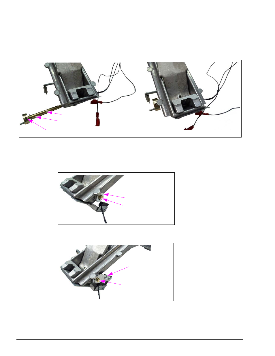
Install the lever shaft. Ensure that the set screw cavity and roll pin point are in the same
direction. This will help with alignment.
Figure 6: Installing Lever Shaft
(i)
(ii)
Set Screw Cavity
Roll Pin to Secure Spring Cam
Lever Shaft
(M14143A001)
4
Install the Spacer Washer (K65235-33), Magnet Bracket Assembly (M14145A001), Nozzle
Bracket Lock Bushing (M14068B001), and Cotter Pin (K02124) to the lever shaft.
Figure 7: Installing Spacer Washer
Spacer Washer (K65235-33)
Lever Shaft (M14143A001)
Figure 8: Installing Magnet Bracket Assembly
Magnet Bracket Assembly
(M14145A001)
Lever Shaft (M14143A001)
Note: The shaft has a D shape end that matches a D shaped hole in the magnet bracket
assembly. These D shapes are supposed to be tight, so carefully and gently wriggle the
bracket onto the shaft. When the magnet bracket assembly is fully onto the shaft, the
lock bushing is in and aligned, the cotter pin should easily go into place. Ensure that
one of the cotter pin legs is bent to secure it in place (see