Gasboy 120VAC Heater Kit User Manual
Page 3
C35403 Rev. 8120
Page 3
10. Remove the four nuts, washers, and lockwashers securing the platform assembly to the chassis. While standing on the
side with the display panel still installed, lift the platform up and out toward you.
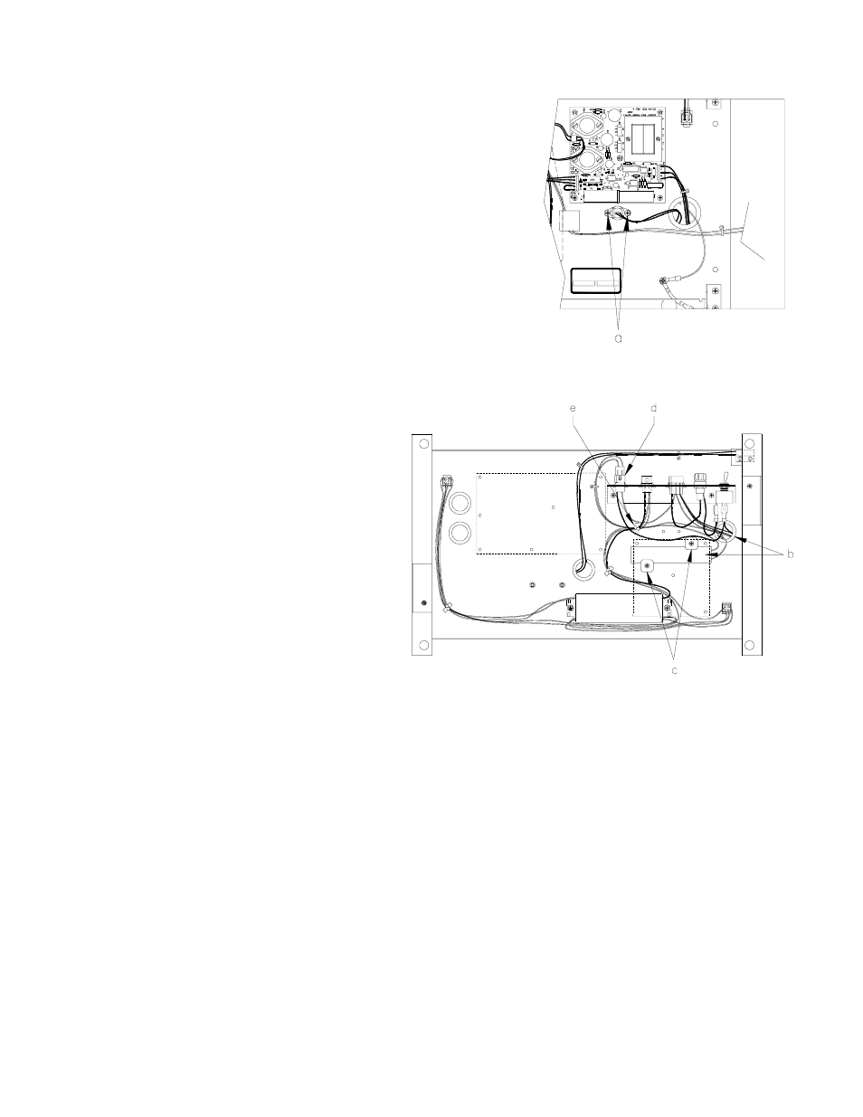
11. Get the heater cable assembly. From the underside of the platform, push
the thermostat up through the bushing and secure it to the standoffs using
the 6-32 screws (a).
12. Remove the adhesive backing from the heater
strip. Press the heater strip to the platform so it is
centered between the two 8-32 weld nuts, with
the heater wires facing the thermostat bushing
(b). Install the fiber washers to hold the heater
strip in place using the 8-32 screws (c). NOTE:
Newer platforms do not have weld-nuts; use #8-
32 self-tapping screws to install fiber washers.
13. Connect the heater cable to the power bracket
connector labeled HEATER (d).
14. Install the nylon tie wrap or wire twist standoff to
secure the heater and ballast cables to the
platform (e).
15. Place the platform assembly back into the chassis. Push the cables up through their appropriate bushings. Install the
four nuts, washers, and lock washers to secure the platform to the chassis.
16. Connect the LIGHTS and MICRO connectors to the power bracket.
17. Attach the AC, pulser, and handle cables to the CPU PCB. Attach the DC cable to the RS-485 PCB or Pump I/F PCB.
On relay 1, connect the red wire to screw #1 and the blue wire to screw #2. On relay 2, connect the orange wire to
screw #1 and the black wire to screw #2.
18. Install the display panel. Attach the ribbon cables to the LCD Display PCBs and the power cables to the LED Backlight
PCBs. Attach the ground braid and connect the fluorescent lamp cable to its mating connector. Secure both display
panels in the upright position.
19. Attach the bezels. Make sure the bezels are seated properly to insure a watertight seal.
20. Attach and lock the front panels.