Model 257-005 – GAI-Tronics 227-005 SMART Auto-Dial Handset Telephones User Manual
Page 16
Pub. 42004-443C
SMART
A
UTO
-D
IAL
H
ANDSET
T
ELEPHONES
P
AGE
14 of 31
f:\standard ioms - current release\42004 instr. manuals\42004-443c.doc
02/13
Model 257-005
1. Open the front door and remove the four outer screws from the mid-section. Carefully pull the
enclosure apart until encountering a slight resistance on the left side.
2. Pull on the left side of the enclosure until the hinge plugs pull loose to separate the front and rear
halves. Set the front half of the enclosure aside.
3. There are four mounting holes in the rear enclosure. Mount the enclosure on the wall using four ¼-20
machine screws with nuts and washers or #14 wood screws of appropriate length for the mounting
surface.
4. Drill a 0.688-diameter hole at either drill spot on the bottom of the rear enclosure, and attach the
gland bushing.
5. Reinsert the hinge pins to attach the front half of the enclosure. Fish the free end of the telephone
cord through the gland bushing.
6. Connect the telephone line to the customer-supplied telephone line surge suppressor (if applicable)
and modular jack (USOC RJ11 or CA11A) provided with the unit.
N
OTE
: The modular jack may be mounted inside the telephone. Telephone line connections directly
to TB1 are acceptable.
7. Allow the telephone a minimum of 35 seconds to initialize.
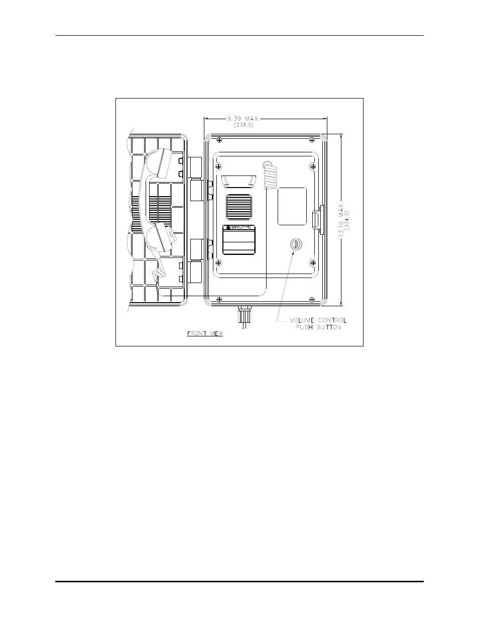
Figure 8. Model 257-005 SMART Auto-Dial Telephone Outline
(Front door open)
- 247-005 SMART Auto-Dial Handset Telephones 277-005 SMART Auto-Dial Handset Telephones 257-005 SMART Auto-Dial Handset Telephones 226-005 SMART Handset Telephones with Keypads 246-005 SMART Handset Telephones with Keypads 276-005 SMART Handset Telephones with Keypads 256-005 SMART Handset Telephones with Keypads