GAI-Tronics 227-005 SMART Auto-Dial Handset Telephones User Manual
Page 13
Pub. 42004-443C
SMART
A
UTO
-D
IAL
H
ANDSET
T
ELEPHONES
P
AGE
11 of 31
f:\standard ioms - current release\42004 instr. manuals\42004-443c.doc
02/13
6. Pull the telephone line through the conduit and into the enclosure. Connect the telephone line to the
customer-supplied telephone line surge suppressor (if applicable) and modular jack (USOC RJ11 or
CA11A) provided with the unit.
N
OTE
: The modular jack may be mounted inside the telephone. Telephone line connections directly
to TB1 are acceptable.
7. Allow the telephone a minimum of 35 seconds to initialize.
8. Using the “Setup” section of this manual,
Configure the hardware as required. Refer to the “Hardware Configuration” section on page 19
for details.
Adjust the audio levels, if necessary. Refer to Figure 13 for Receiver Volume and Microphone
Sensitivity potentiometer locations.
9. Verify operation by calling to and from another telephone.
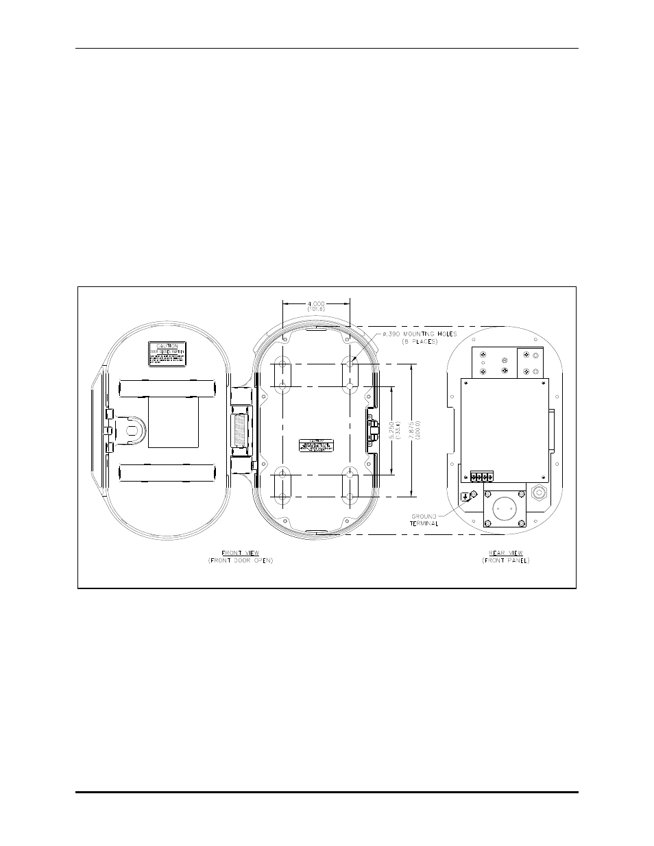
Figure 5. Model 227-005 Mounting Details
10. Replace the front panel assembly, and secure using the eight front panel security screws.
- 247-005 SMART Auto-Dial Handset Telephones 277-005 SMART Auto-Dial Handset Telephones 257-005 SMART Auto-Dial Handset Telephones 226-005 SMART Handset Telephones with Keypads 246-005 SMART Handset Telephones with Keypads 276-005 SMART Handset Telephones with Keypads 256-005 SMART Handset Telephones with Keypads