Limitorque actuation systems, Flow control – Flowserve MX-85 Actuator User Manual
Page 69
Flow Control
Limitorque Actuation Systems
FCD LMAIM1341-00
MX-85/140 Maintenance and Spare Parts
61
• This serial number is located on the second screen after the “Restricted Settings” screen. It is an eight digit num-
ber after the letters “S/N”. Please refer to the IOM manual, LMAIM1306, supplied with your actuator for the Menu
sequence.
• User must supply this number. Example: 12345678
• Also record the Order Number and Serial Number of the actuator. These numbers can be found on the unit nameplate.
• Once you have acquired the QA Stamp, O/N and S/N, please contact your assigned Service Coordinators for the
keycodes required to turn-on the desired options @ (434) 528-4400.
• The “keycode” is then entered into the desired option menu found in “Restricted Settings” using the black knob on
the ACP. A “NO” answer will change the value form 0-9 and A-E. A “YES” answer will truncate to the next space.
• After enabling the Modutronic option, please change the remote control wiring scheme to “3-wire maintained.”
• For adding the APT, ATT, and AR options, the I/) option board is required. When the I/O board is received and installed
into the actuator, it will already have the option(s) enabled. The unit will recognize the board and turn on the required
software menu feature. Please refer to the IOM manual, LMAIM1306, supplied with your actuator for the Menu
sequence. The user will need to enable the menu options. Please contact your assigned Service Coordinators for
purchase of these desired options @ (434) 528-4400.
• For adding the DDC or FF option, the DDC or FF option board is required. When the DDC option board is received and
installed into the actuator, it will recognize the board and turn on the required software menu feature. Please refer to
the IOM manual, LMAIM1306, supplied with your actuator for the Menu sequence. The user will need to enable the
menu options. Please contact your assigned Service Coordinators for purchase of the DDC option @ (434) 528-4400.
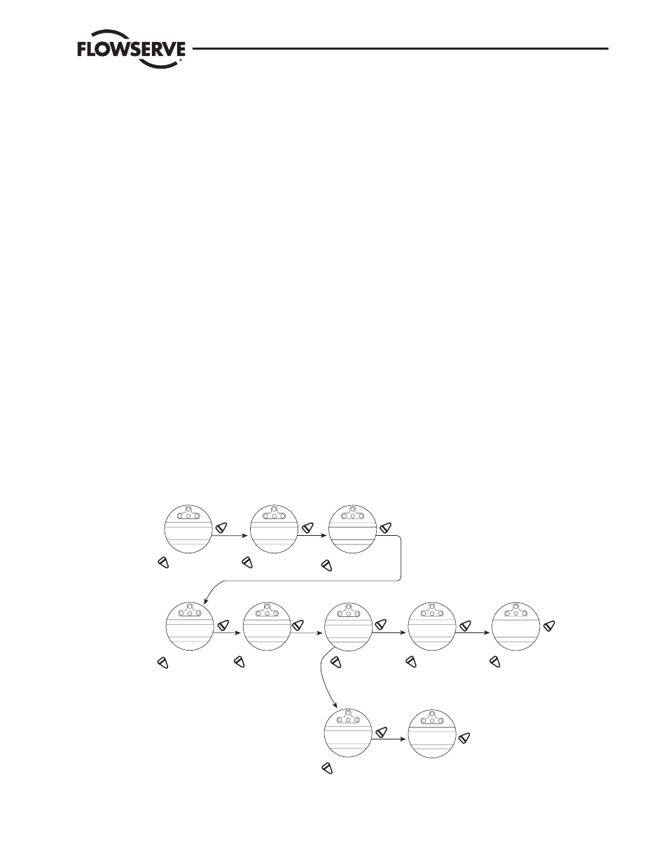
5.4 Restoring Power to Actuator with New Control Module
Figure 5.3 – Restoring Power to Actuator with New Control Module
Yes
No
No
Yes
No
No
Yes
Yes
Yes
No
No
Yes
Yes
UNIT SIZE
MX-05-OK?
VOLTAGE
460 VOLT-OK?
Hz
60 Hz-OK?
ACTUATOR RPM
12/18-OK?
S/N
0------OK?
COLD (-50ºC) UNIT
YES/NO -OK?
LOAD DEFAULT
UNIT SETTINGS?
INITIALIZE?
LOAD COLD TEMP
DEFAULTS?
INITIALIZE?
Answer “No” until the
correct unit size is
displayed. Refer to
nameplate.
Answer “No” until
the correct voltage
is displayed. Refer
to nameplate.
Answer “No” until
the correct frequency
is displayed. Refer to
nameplate.
Answer “No” until
the correct RPM
is displayed. Refer
to nameplate.
Answer “No” until the
value is displayed and
then “Yes” to enter.
Refer to namplate for
S/N.
Answer “No” to
select normal
temperature
parameters, -
30ºC to +70ºC.
Answer “Yes” to select arctic
temperature parameters, -
-50ºC to +60°C.
Answer “Yes” to
load default
settings. Unit will
now have factory
default settings.
Please refer to Limitorque Accutronix
MX Customer Connection(s) Diagram
(#L2180) reverse side (located on the
inside of the terminal compartment
cover) for customer default
configuration.
Answer “No”
to change.
Answer “Yes”
to save
settings.
Answer “No”
to change.
Answer “Yes”
to load cold
temperature defaults.
Answer “No”
to change.
Answer “Yes”
to save
settings.
No
Yes
No
Yes
No
Yes