Flowserve MX-85 Actuator User Manual
Page 66
Flow Control
Limitorque Actuation Systems
58
MX-85/140 Maintenance and Spare Parts
FCD LMAIM1341-00
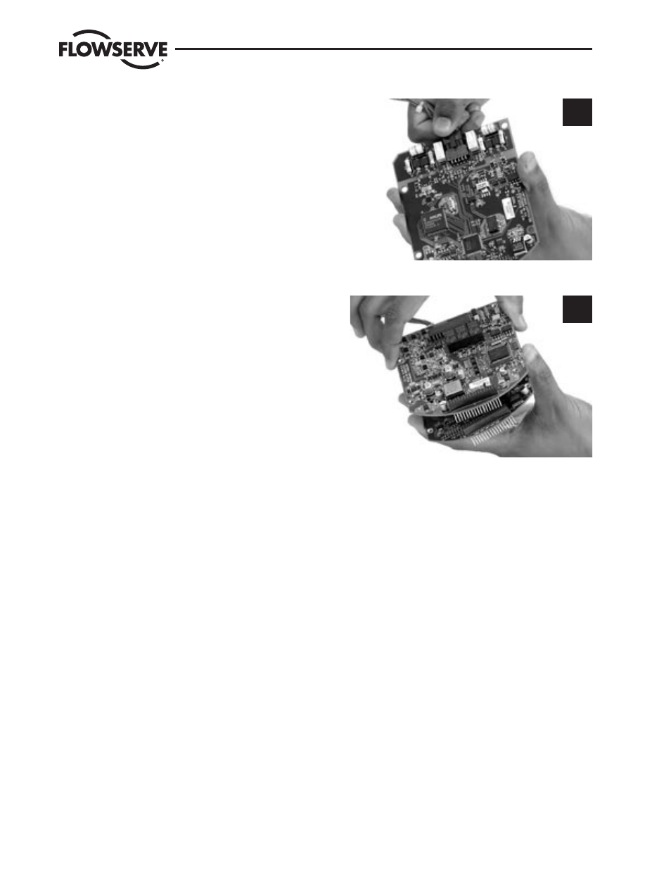
STEP 9
If DDC, Foundation Fieldbus H1 or Profibus DP/PA
board is installed, stack the network board onto
the Main/LCS board (or I/O option board) assuring
proper mating of the board to board connector P1.
Connect 10-pin Molex harness to plug P2 on these
boards (network processor board).
9
STEP 10
If I/O option board is installed, stack the I/O option
board onto the Main/LCS board assuring proper
mating of the board to board connector P2. Con-
nect 24-pin Molex harness to plug P1 on I/O option
board.
NOTE: If network or I/O option boards are installed,
they may be stacked on the Main/LCS board in any
order.
10
STEP 11
Before mounting the LCS/Main processor board
into the ACP, replace the knobs per instructions
#102254 (supplied with the knob conversion kit).
NOTE: Applies only to version 1 of
ACP (V1 = triangle-shaped knobs)
Mount the LCS/Main processor board inside the
ACP cover as follows: