2 installation and removal of smt controls, 1 installation – Flowserve MX-85 Actuator User Manual
Page 64
Flow Control
Limitorque Actuation Systems
56
MX-85/140 Maintenance and Spare Parts
FCD LMAIM1341-00
5.2 Installation and Removal of SMT Controls
5.2.1 Installation
STEP 1
a
CAUTION: Ensure the voltage jumper on power
board is located in the proper slot for the
nameplate and motor voltage! Follow the tem-
plate provided on the Mylar protection barrier
for proper voltage jumper location.
a
CAUTION: Potential to cause electrostatic
damage to electronic components. Before
handling electronic components, ensure that
you are discharged of static electricity by briefly
touching a grounded metal object. Flowserve
recommends the use of a wrist strap grounded
to an appropriate ground.
1
STEP 2 (IF NECESSARY)
Attach the SMT Terminal Block conversion wiring
harness (P/N 64-825-0010-4) to the existing
through hole wiring harness. Connect each through
hole Molex connector to its corresponding SMT
Molex connector.
STEP 3
Install tie wrap on the mated 20 pin Molex connec-
tor pair so that they cannot be separated.
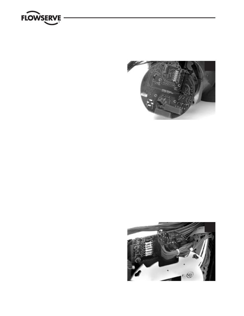
STEP 4
Connect the 6-pin Molex wire harness to plug P2
and 16-pin Molex harness to plug P3, and the 20
pin Molex wire harness to plug P4 on Power board.
4