4 input/output data, 4 input/output data -3 – Delta Electronics DeviceNet CME-DN01 User Manual
Page 13
Chapter 3 Quick Start| CME-DN01
Revision October 2007, 2006PDD23000003
3-3
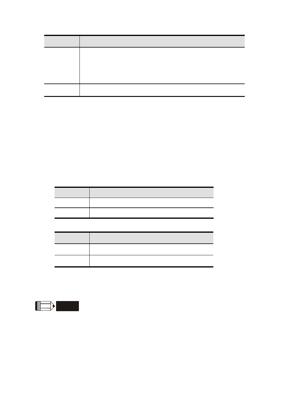
Address
Description
0-63
All addresses should be set within this range. Before setting
address, please make sure that the address you want to use is
available (NOT used by others). The address cannot be used
repeatedly. Or it cannot connect to the network and the NET LED
will be RED.
64-99
This range is illegal addresses and the NET LED will be RED.
Example: ADD1: 3, ADD2: 6, Data Rate: 500k.
Then the value of MAC ID is 36, not 0x36; the Baud rate is 500K.
3.4 Input/Output Data
Default settings of I/O poll message are 4 bytes input and 4 bytes output data.
The information in the following tables is an example:
Input data from AC drivers to DeviceNet (read only)
Word
Function Description
0
Status of AC Driver (2101H)
1
Frequency Command (2102H)
Output data from DeviceNet to AC drivers
Word
Function Description
0
Operate Command (2000H)
1
Frequency command (2001H)
Refer to each AC drive user manual for setting above table.
NOTE
If CME-DN01 has not been set before using, you can use it by connecting with DeviceNet
network without any settings. In this case, CME-DN01 provides a default I/O setting as table
above. CME-DN01 will use this default setting to exchange data with network in I/O message
when power up. Please refer to Chapter 4 Configuration if a desire I/O setting is needed.