Rb rc mo1 mcm rj11 – Delta Electronics Network Device VFD-S User Manual
Page 7
English- 7
Terminal Explanations
Terminal Symbol
Explanation of Terminal Function
R/L1, S/L2, T/L3
AC line input terminals (three phase)
L/L1, N/L2
AC line input terminals (single phase)
U/T1, V/T2, W/T3
Motor connections
+2/B2 – B1
Connections for Braking Resistor (optional)
+2/+1 – B1
Connections for DC Link Reactor (optional)
Earth Ground
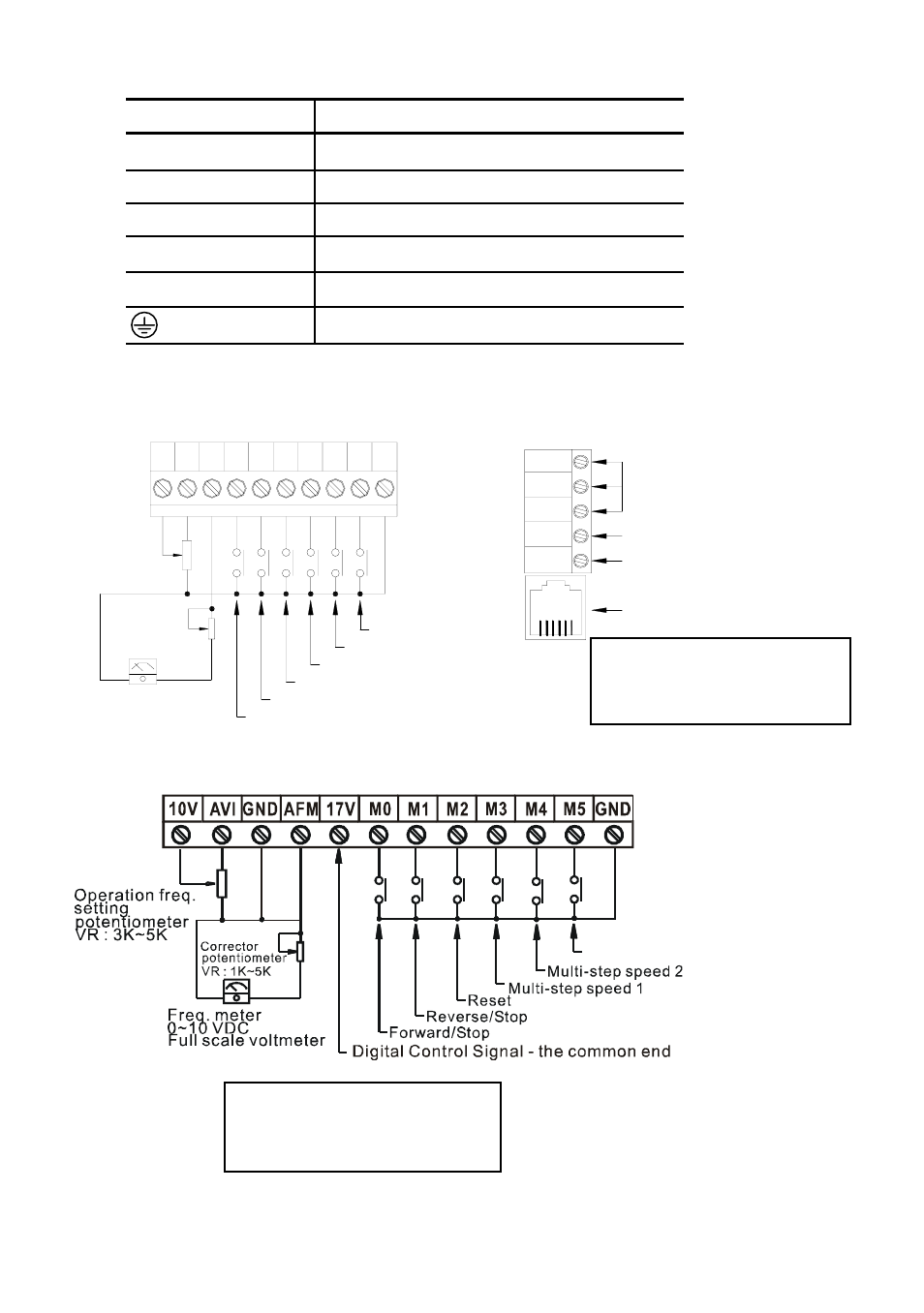
Control Terminal Wiring (Factory Setting)
A. XXXSXXA/B/D/U
RA
M1
AVI
10V
+
AFM M0
M4
M2 M3
M5
GND
RB
RC
MO1
MCM
RJ11
Multi-step speed 3
Multi-step speed 2
Multi-step speed 1
Reset
Reverse/Stop
Forward/Stop
Corrector
potentiometer
VR : 1K~5K
Freq. meter
0~10 VDC
Full scale voltmeter
Operation freq.
setting
potentiometer
VR : 3K~5K
Relay contactor output
Factory setting : Fault indication
Photo coupler output
Factory setting : in work
6 ~ 1
RS485 Communication port
B. XXXSXXE
Multi-step speed 3
*
*
Wire Gauge: 24-12 AWG
Wire Type: Copper Only
Torque: 4 kgf-cm (3.5 in-lbf)
Wire Gauge: 24-16 AWG
Wire Type: Copper Only
Torque: 2 kgf-cm (1.7 in-lbf)
- 1x9 Bi-Directional Transceiver Module OPBD-155F2J1R (7 pages)
- Single Mode SFP Transceiver LCP-1250B4MDRx (14 pages)
- LC-1250xxxx Series (10 pages)
- Human Machine Interface DOP-AS Series (329 pages)
- Analog Output Module DVP04DA-S (2 pages)
- DeviceNet Slave Communication Module IFD9502 (2 pages)
- LCP-155B4MSRx (12 pages)
- High-Speed PCI 12-Axis Motion Control Card PCI-DMC-B01 (528 pages)
- Network Device DVP01PU-S (2 pages)
- GBIC-1250D5MR (12 pages)
- SPBD-1250A4Q1RT (10 pages)
- SILM4015 (1 page)
- LCP-8500A4EDR (14 pages)
- 10GBASE-SR SFP+ Optical Transceiver LCP-10G3A4EDR (16 pages)
- LCP-155A4HSRx (11 pages)
- LCP-1250RJ3SR-L (9 pages)
- SILM320L (1 page)
- LCP-1250RJ3SR-S (9 pages)
- SIL530 (1 page)
- Extension Digital I/O Module DOP-EXIO28RAE (1 page)
- DVP Series PLC DVP04TC-H2 (2 pages)
- 1x9 Bi-Directional Transceiver Module OPBD-155F1J1R (7 pages)
- Distribution Box TAP-CN01/02/03 (2 pages)
- LCP-200A4HSR (9 pages)
- Pulse Generation Unit DVP01PU-H2 (2 pages)
- Power Connection Interface VFD-PSD01 (1 page)
- Programmable Logic Controller DVP04DA-H2 (2 pages)
- Single Mode SFP Transceiver LCP-1250B4QDRx (13 pages)
- LCP-155B4JSRx Series (12 pages)
- Series Temperature Controller DTD Series (2 pages)
- Brake Modules BUE Series (2 pages)
- PLC DVP Series DVP-SX (2 pages)
- Digital Keypad / Display ASD-PU-01A (1 page)
- Multimode SFP Transceiver LCP-1250A4FDRx (14 pages)
- HMU1362M (1 page)
- RPA-01 (1 page)
- THMR1395 (1 page)
- SFBD-155F2J1RM (7 pages)
- Program Transfer Module DVP-PCC01 (1 page)
- RTU-DNET (41 pages)
- AC Servo Drive ASDA-AB (37 pages)
- Digital Keypad / Display ASD-PU-01B (1 page)
- HMR1045 (1 page)
- CANopen Communication Module DVPCOPM-SL (2 pages)
- SPBD-1250B4Q1R (10 pages)