Delta Electronics Network Device VFD-S User Manual
Page 18
English- 18
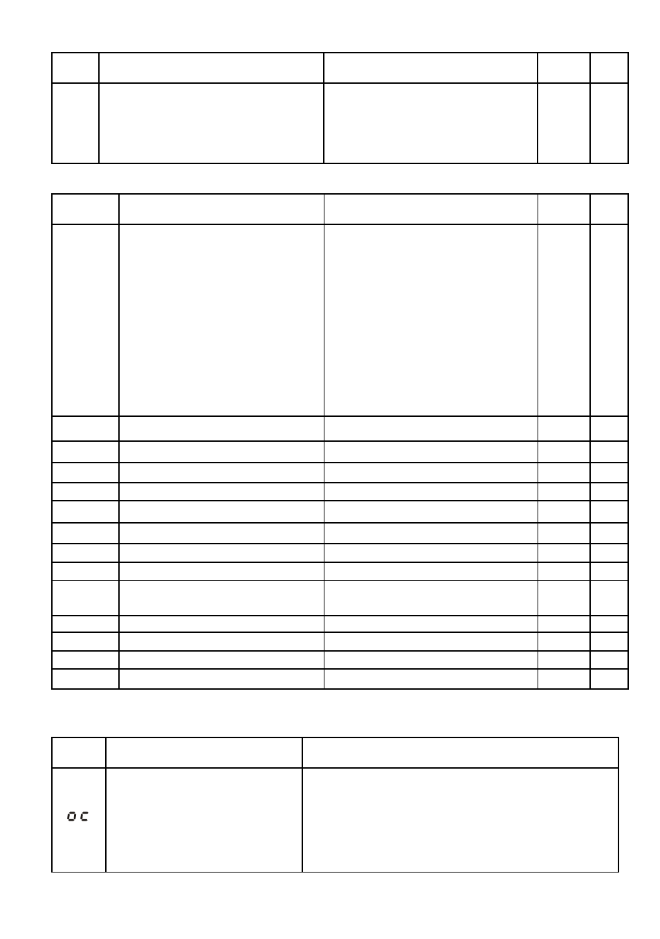
Pr. Explanation
Settings
Factory
Setting
NOTE
d4: 8,E,1 (Modbus, ASCII)
d5: 8,O,1 (Modbus, ASCII)
d6: 8,N,2 (Modbus, RTU)
d7: 8,E,1 (Modbus, RTU)
d8: 8,O,1 (Modbus, RTU)
Group A PID Parameters
Pr. Explanation
Settings
Factory
Setting
NOTE
A-00
Input terminal for PID Feedback
d0: Disable PID function
d1: Negative PID feedback from
external terminal (AVI) 0 to
+10V
d2: Negative PID feedback from
external terminal (ACI) 4 to
20mA
d3: Positive PID feedback from
external terminal (AVI) 0 to
+10V
d4: Positive PID feedback from
external terminal (ACI) 4 to
20mA
d0
A-01
Gain over PID Detection value
d0 to d999
d100
A-02
Proportional Gain (P)
d0 to d999
d100
A-03
Integral Time (I)
d0 to d999
d100
A-04
Derivative Control (D)
d0 to d100
d0
A-05
Upper Bound for Integral Control
d0 to d100%
d100
A-06
Primary Delay Filter Time
d0 to d999
d0
A-07
PID Output Freq. Limit
d0 to d110%
d100
A-08
Feedback Signal Detection Time
d0.0 to d650 seconds
d0.0
A-09
Treatment of the Erroneous
Feedback Signals
d0: warn and RAMP to stop
d1: warn and COAST to stop
d0
A-10
Sleep Frequency
d0.0 to d400Hz
d0.0
A-11
Wakeup Frequency
d0.0 to d400Hz
d0.0
A-12
Sleep Period
d0.0 to d650 seconds
d0.0
A-13
PID User Defined
d0.0 to d400
d0.0
Fault Codes
Fault
Name
Fault Descriptions
Corrective Actions
Over current
Abnormal increase in current.
1. Check if motor power corresponds with the AC
motor drive output power.
2. Check the wiring connections to U/T1, V/T2,
W/T3 for possible short circuits.
3. Check the wiring connections between the AC
motor drive and motor for possible short
circuits, also to ground.