Signal connections between sections – Daktronics GPR-12EV-RGB User Manual
Page 24
18
Signal Installation
4.2 Signal Connections Between Sections
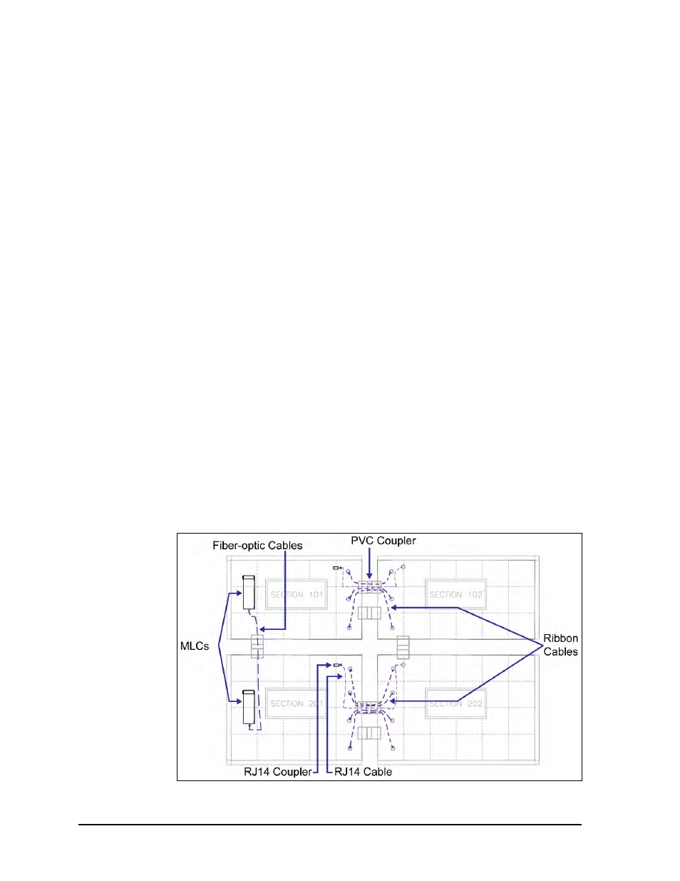
Fiber-optic cable must be connected between each first (left) section’s Multi-Line Controller
(MLC). If additional sections are added for width ribbon cables must be connected between
modules as well as an RJ11 cable between sections. Refer to Figure 20 for an example.
To connect MLCs:
1. A fiber-optic cable will be connected to the upper MLC(s).
2. Route the fiber-optic cable from the upper MLC through the PVC coupler to the
lower MLC.
3. Connect the fiber-optic cable to the J24 jack on the lower MLC.
To connect additional sections added for width:
1. Ribbon cables will be attached to modules in subsequent sections. There will also be
an RJ11 cable located in the upper left corner of the subsequent sections.
2. Route the ribbon cables from the subsequent modules through the upper PVC
coupler to the adjacent modules in the previous section. Also route the RJ11 cable to
the upper right corner of the previous section.
Note: Signal cables and power wires must not be routed through the same PVC
coupler.
3. Connect the ribbon cables to the open jacks on the first sections’ modules.
4. Connect the RJ11 cable to the RJ11 coupler.
Figure 20: Section Signal Connections