Daktronics AF-3010-34 User Manual
Page 56
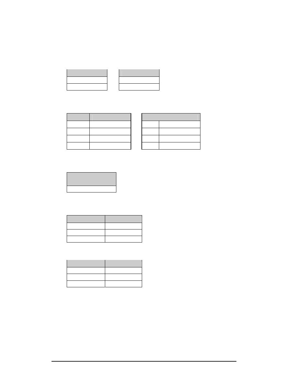
Loop-Back Test: To perform a loop-back, for testing purposes only, connect the following
using copper conductor jumpers.
Note: This test should be performed with only one jack at a time. Do not connect loop back to
more than one jack at a time.
J2 and J3
J4 and J5
TX-N to RX-N
OR
RX-P to TX-P
TX-P to RX-P
RX-N to TX-N
0A-1127-0239 – Fiber
The following tables give the jack pin-outs for a fiber signal converter.
JACK
OPERATION
J1 – 25 Pin DB-F
J2 TX1
(out)
PIN OPERATION
J3 RX1
(in)
2 TX-P
(out)
J4 TX2
(out)
3 RX-P
(in)
J5 RX2
(in)
7 GND
Loop-Back Test: To perform a loop-back, for testing purposes only, connect the following
using a fiber optic cable jumper.
J2 and J3 or J4
and J5
TX to RX
Serial Cable (W-1249)
This table lists the pin connections when using a serial cable (W-1249).
DB9-F
DB25-F
Pin 3 – TX
Pin 2 – TX
Pin 2 – RX
Pin 3 – RX
Pin 5 – GND
Pin 7 - GND
Serial Adaptor (A-1603)
DB9-F
DB25-M
Pin 3 – TX
Pin 2 – TX
Pin 2 – RX
Pin 3 – RX
Pin 5 – GND
Pin 7 - GND
Appendix B: Signal Converter
B-2
- TI-3031 4-Inch LED Bar-Digit Locker Room Clock (22 pages)
- ST-2005 Backlit & Non-Backlit Scorer’s Tables (24 pages)
- BB-2135 Backboard LED Light Strip (36 pages)
- TN-2563 Tuff Sport Indoor Multi-Court Tennis LED Scoreboard (112 pages)
- BB-2144 Tuff Sport Basketball LED Scoreboard (184 pages)
- TN-2607 Single-Court Outdoor LED Tennis Scoreboard (134 pages)
- CR-2004 Multi-Section Cricket Scoreboard (90 pages)
- FT-7150 Touchpad (29 pages)
- SW-2008 Aquatics/Track LED Scoreboard (84 pages)
- SO-1424-11 Multi-Section Outdoor LED Scoreboard (158 pages)
- FB-4005-31 DistaView Outdoor LED Scoreboard (64 pages)
- MS-2018 Generation III Stackable LED Scoreboard (76 pages)
- GM-2103 LED Gymnastics Scoreboards (38 pages)
- HS-200 Horn Start (36 pages)
- Indoor Hockey Goal Lights (44 pages)
- LED End-of-Period Basketball Lighting (34 pages)
- MS-2013 Portable LED Scoreboard (52 pages)
- WR-2106 Matside Jr. LED Wrestling Scoreboard (44 pages)
- TI-2021 Multipurpose Track & Field LED Timing Display (50 pages)
- P1647 Multi-Section Outdoor LED Scoreboard (52 pages)
- P1647 Multi-Section Outdoor LED Scoreboard (50 pages)
- DA-1200 Outdoor Decorative Accent (30 pages)
- 2000 Rodeo OmniSport (72 pages)
- Outdoor LED Scoreboards Installation (58 pages)
- Outdoor LED Scoreboards Service Manual (52 pages)
- SO-2014 Generation IV Multi-Section Outdoor LED Scoreboard (208 pages)
- P1647 Multi-Section Outdoor LED Scoreboard (44 pages)
- PC-2001 Pace Clock System (40 pages)
- PC-2002 Pace Clock System (32 pages)
- BB-314 Portable LED Basketball Scoreboard (28 pages)
- Protective Screen (4 pages)
- TI-2002 Portable LED Timer (32 pages)
- Radar Gun Speed of Pitch Interface (27 pages)
- TI-2026 Segment Timer (28 pages)
- Single-Section Outdoor LED Scoreboards (46 pages)
- LED Aquatics/Track Displays SW-2000 Series 10 Numeric Digit (86 pages)
- TI-2022 Portable LED Timer (32 pages)
- Single Section DistaView Outdoor LED Scoreboards Generation IV (99 pages)
- BB-2151 (NBA only) Transparent Shot Clock (48 pages)
- TN-2563 Tuff Sport Indoor LED Tennis Scoreboard (34 pages)
- Scoreboard Trumpet Horn (50 pages)
- ST-3001 Tuff Sport & ColorSmart LED Scorer’s Table (48 pages)
- Tuff Sport & ColorSmart Indoor LED Scoreboards (46 pages)
- Tuff Sport Indoor LED Scoreboards (40 pages)
- Tuff Sport& ColorSmart FourSided Indoor LED Scoreboards (58 pages)