Controller address and test mode, Controller address and test mode -5, Figure 30: location of dip switches -5 – Daktronics AF-3010-34 User Manual
Page 41
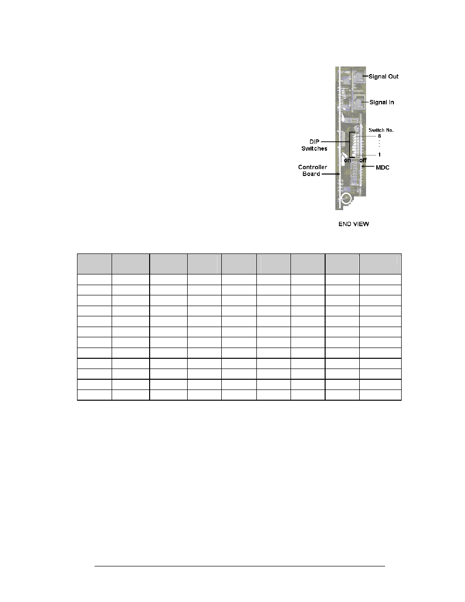
Controller Address and Test Mode
Before a display can be run in a sign network, it must
have an address. The display address can be set using
“DIP” switches located on a PC board known as the
MDC. The MDC is the circuit card mounted in the
lower right corner of the controller board.
Figure 30: Location of DIP
Switches
Locate the DIP switches on the MDC. They should be
on the bottom end of the card. Refer to Figure 30 on
the right for a picture of the DIP switches.
When replacing a controller board, be sure to set the
DIP switches to the same address configuration as the
defective controller. The DIP switches follow standard
binary code.
Note: By setting the DIP switches to address 0 (flip all
the switches toward the numbers on the circuit board),
a test mode can be activated. The display’s power must
be downed, and then reconnected to run the test mode.
Switch
8
Switch
7
Switch
6
Switch
5
Switch
4
Switch
3
Switch
2
Switch
1
Address
Off Off Off Off Off Off Off On 1
Off Off Off Off Off Off On Off 2
Off Off Off Off Off Off On On 3
Off Off Off Off Off On Off Off 4
Off Off Off Off Off On Off On 5
Off Off Off Off Off On On Off 6
Off Off Off Off Off On On On 7
Off Off Off Off On Off Off Off 8
Off Off Off Off On Off Off On 9
Off Off Off Off On Off On Off 10
… … … … … … … …
Off On On On On On On On 127
Maintenance and Troubleshooting
4-5