Light detector, Transformer, Modem – Daktronics AF-3010-34 User Manual
Page 42: Accessing and replacing the modem, Light detector -6, Transformer -6, Modem -6, Accessing and replacing the modem -6, Figure 31: modem -6, 7 transformer
Light Detector
Reference Drawings:
Shop Drawing..................................................... Refer to Appendix C
Schematic .......................................................... Refer to Appendix C
The light detector is internally mounted and wired at Daktronics. It is located on the
lower left of the display (refer to Detail A in shop drawings). A 4-conductor cable is
used to connect the light detector to the controller board. The cable is terminated at
the terminal block on the light sensor and at the terminal block on the controller
board (refer to schematics).
Light Detector
Pin No.
Cable Wires
Color
Controller Board
Pin No.
1 Green 3
2 White 4
3 Red 1
4 Black 2
N.C. Bare
2
4.7 Transformer
The transformer is used to provide power to the controller board 10-12 VAC,
modem, fiber converter, or radio depending on the communication method used. It is
located in the bottom left corner (front view) of the display in the power termination
box.
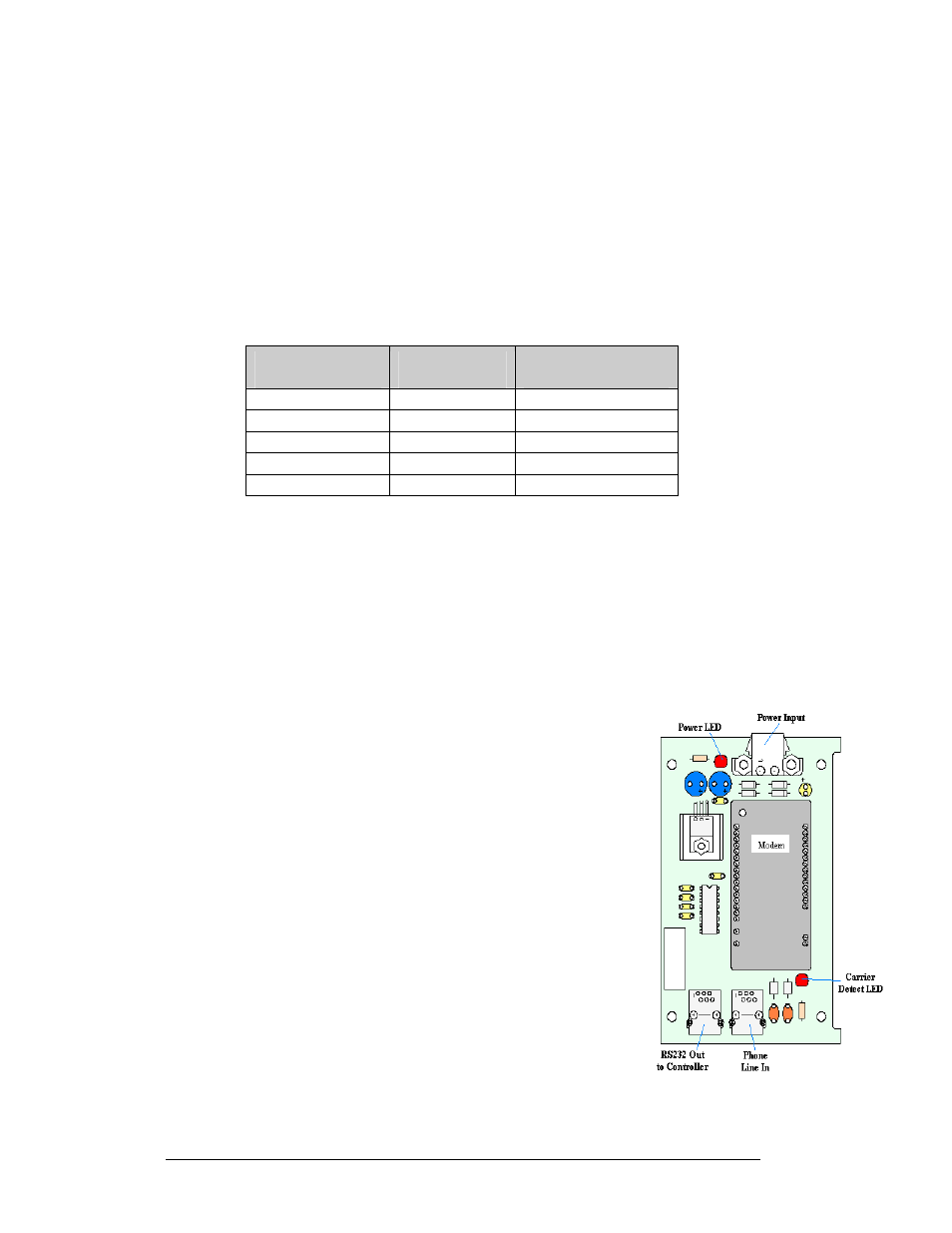
4.8 Modem
Figure 31: Modem
Accessing and Replacing the Modem
If a modem was included with the display, it is located inside the
sign next to the controller board. Tools required: 8mm Allen
wrench, 5/16" nutdriver, and 3/16" nutdriver
1. Open display and remove the module in front of the
modem in the lower left corner.
2. To replace a modem, first disconnect the power and
signal connections (refer to Figure 31 on the right for
the location of the power jack).
3. The modem is held in place with four 3/16" screws.
Remove these four screws and carefully remove the
modem.
4. Place the new modem over the four screws and replace
the screws. Reconnect the power and signal connections.
Maintenance and Troubleshooting
4-6