Radio, Radio -10, Figure 21: fiber optic layout -10 – Daktronics AF-3010-34 User Manual
Page 32
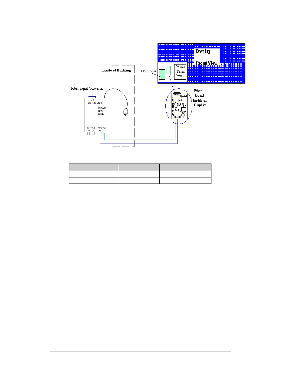
Figure 21: Fiber Optic Layout
Signal Converter
Field Cabling
Display Fiber Board
J2 Transmit (TX)
(color varies)
J5 Receive (RX)
J3 Receive (RX)
(color varies)
J4 Transmit (TX)
Radio
A display that is controlled using a radio requires a server radio connected to the
control computer and a client radio at the display. The radios must be in line-of-sight
with each other.
1. Connect a DB9M to DB9 serial cable from the computer to the J-box. Use
6-condutor, 18-gauge cable, to connect from the J-box to the Server radio.
The cable must be in conduit when exposed to outdoor conditions. The
distance from the J-box to the Server radio should not exceed 1000 feet.
Figure 22 on the following page shows the connections from the J-box to
the server radio.
2. Route the cable provided with the Client radio into the display through one
of the knockouts on the back of the display. Terminate the three signal
wires, and connect the power plug from the Client radio to the additional
jack in the display. Figure 23 on the following page shows the connection
from the client radio to the display.
3. Refer to Drawing A-185325 and the radio manual (ED-13932) for the
correct cable terminations.
Electrical Installation
3-10