Display access/module removal, Led driver replacement, Display access/module removal -2 – Daktronics AF-3010-34 User Manual
Page 38: Led driver replacement -2, Figure 25: removing the mounting nuts -2, Figure 26: removing the module -2, Figure 27: removing the signal connections -2, 3 display access/module removal, 4 led driver replacement
4.3 Display Access/Module Removal
To access the display’s interior electronic components, open the face panel and
remove the appropriate modules. The Galaxy displays are front access. Tools
needed: 8mm Allen wrench and 5/16" nutdriver
1. Release the face panel latches using an 8mm Allen wrench (provided by
Daktronics).
2. Open the face panel. Gas springs will hold the door open for servicing.
Caution: The door will swing up. Take extra precautions during windy
conditions.
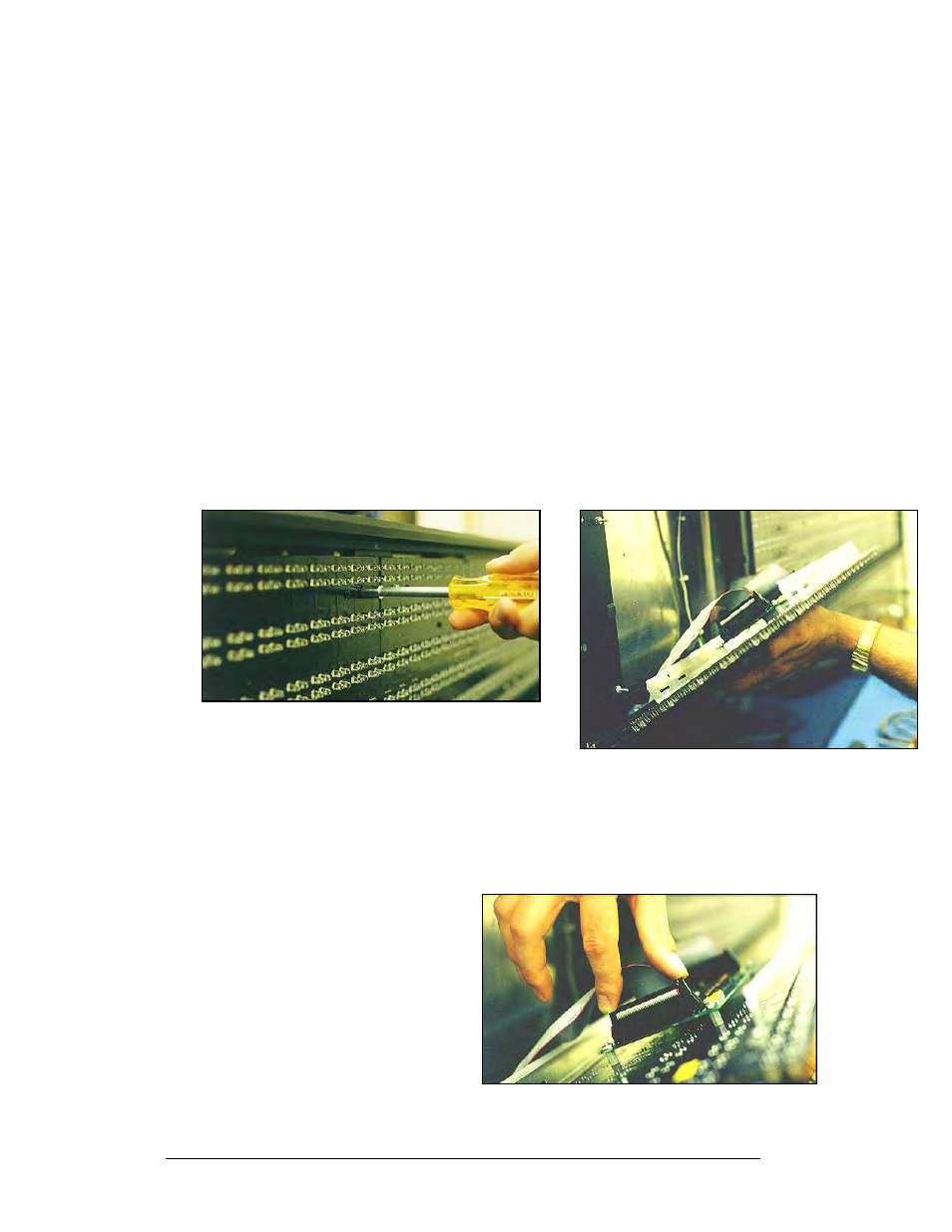
3. Remove the four 5/16" mounting nuts holding the module to the display.
Each mounting nut is located in one corner of the module (refer to Figure
25 below on the left).
4. Carefully pull the module forward to unplug the power/signal connections
(refer to Figure 26 below on the right).
To install or replace the modules, follow the previous steps in reverse order.
Figure 26: Removing the Module
Figure 25: Removing the Mounting Nuts
4.4 LED Driver Replacement
The LED driver is located on the rear side of the module: Tools needed: 8mm Allen
wrench and 5/16" nutdriver
1. Open the display, and release
the module.
Figure 27: Removing the Signal Connections
2. Remove all power and signal
connection from the driver.
By pressing outward on the
locking tabs and gently
pulling the connector free, the
connectors are released (refer
to Figure 27 on the right).
3. Remove the four 5/16" nuts
from the corners. (Some
drivers are held in place by
plastic mounts.)
Maintenance and Troubleshooting
4-2