Signal termination from computer to display, Rs232, Signal termination from computer to display -7 – Daktronics AF-3010-34 User Manual
Page 29: Rs232 -7, Figure 18: rs232 connections -7, 6 signal termination from computer to display
3.6 Signal Termination from Computer to Display
Reference Drawings:
System Riser Diagram, Modem ..................................... Drawing A-88426
System Riser Diagram, Power/Signal V1500 Displays .. Drawing A-88427
System Riser Diagram, RS422 ...................................... Drawing A-92681
System Riser Diagram, RS232 ...................................... Drawing A-96058
System Riser Diagram, Fiber ....................................... Drawing A-110559
System Riser Diagram, Outdoor Radio, Gen 2 ............ Drawing A-185325
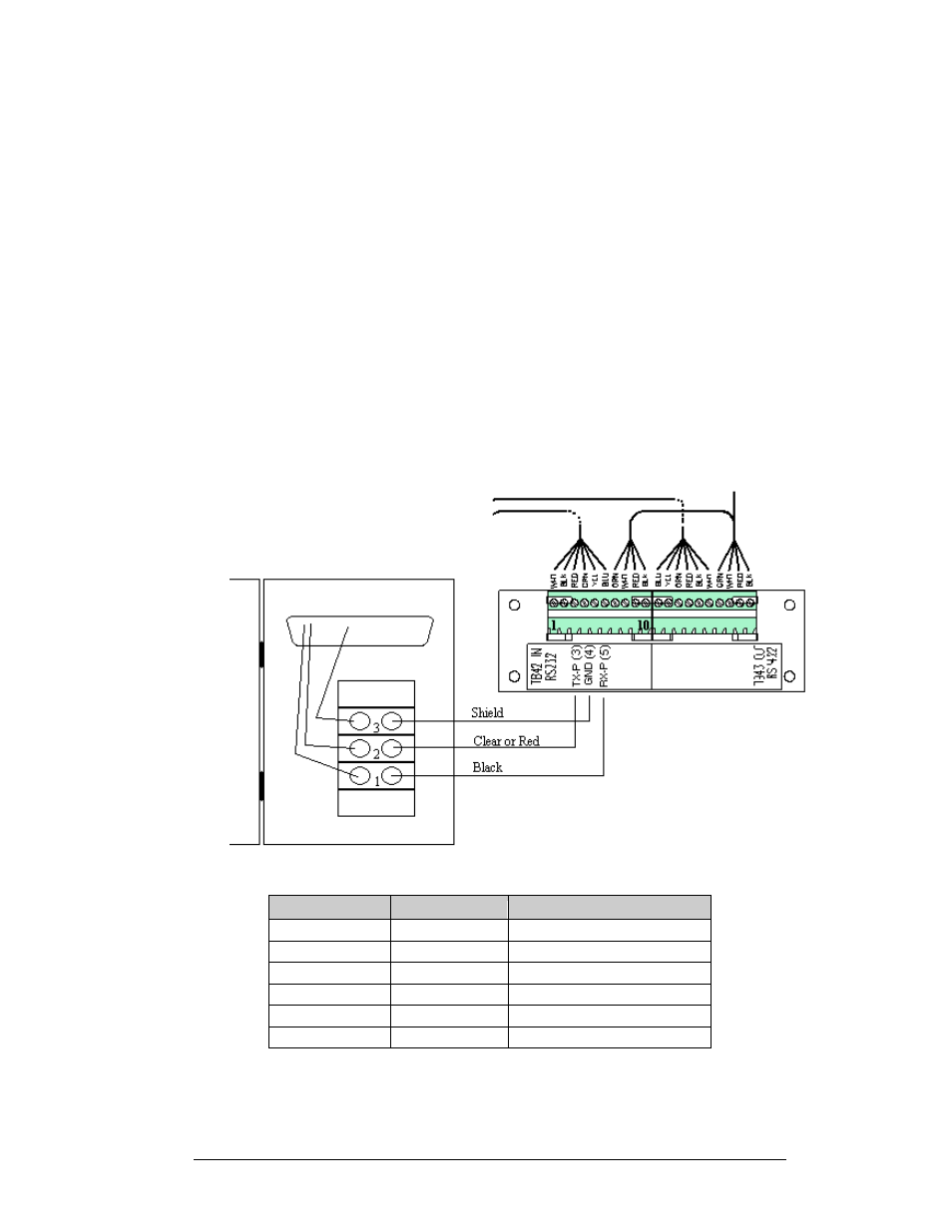
RS232
One end of the signal cable should be terminated to the 10 position terminal block in
the display labeled “IN RS232” (TB42). Drawing A-88427 is an example of the
termination panels. The opposite end is terminated at the J-box at the display
structure. The laptop PC connects to the J-box through the serial cable (refer to
Drawing A-96058).
Figure 18: RS232 Connections
J-Box
Field Cabling
Terminal Block (Data In)
-
-
Pin 1 (N.C.)
-
-
Pin 2 (N.C.)
Pin 2 (RX-P)
Clear
Pin 3 (TX-P)
Pin 3 (GND)
Shield
Pin 4 (GND)
Pin 1 (TX-P)
Black
Pin 5 (RX-P)
-
-
Pin 6 (N.C.)
Electrical Installation
3-7