Conduit, Conduit -3, Figure 15: flipped cable with rj connectors -3 – Daktronics AF-3010-34 User Manual
Page 25: 3 conduit
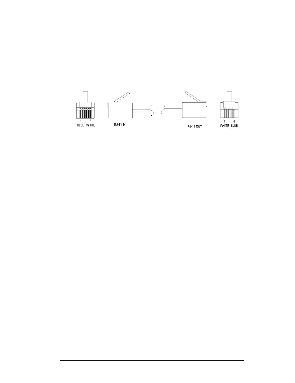
Notice below in Figure 15 that the color code on one connector must be made the
opposite on the other connector. When installing a network, it is not easy to
remember in which direction the previous end was oriented. One simple way to avoid
confusion is to standardize the color code, having one color for the connector going
into the output of a sign, and the opposite color for a connector going into the input
of a sign. This will help ensure correct cabling since cables are always installed from
the output jack of one sign to the input jack of the next sign.
Figure 15: Flipped Cable with RJ Connectors
3.3 Conduit
Reference Drawings:
System Riser Diagram, Modem ..................................... Drawing A-88426
Power/Signal Termination Panel.................................... Drawing A-88427
System Riser Diagram, RS422 ...................................... Drawing A-92681
System Riser Diagram, RS232 ...................................... Drawing A-96058
System Riser Diagram, Fiber ....................................... Drawing A-110559
System Riser Diagram, Outdoor Radio, Gen 2 ............ Drawing A-185325
Shop Drawing............................................................Refer to Appendix C
Daktronics does not include the conduit. Knockouts will be provided for power and
signal. Separate conduit must be used to route:
·
Power
·
Signal IN wires
·
Signal OUT wires (if signal is required for another display)
The conduit holes are located at the bottom right (rear view) of the back of the
display (refer to shop drawings located within Appendix C).
To access the knockouts, release the face panel latches using an 8mm Allen wrench
(provided by Daktronics). Open the face panel. Caution: The door will swing up.
Remove the bottom left module (front view) to reach the knockouts (refer to Section
4.3 to remove a module).
Punch or drill out the desired knockouts. Be careful that none of the internal
components are damaged. Attach the conduit and route the power and signal cables.
Refer to Drawing A-88427 for a picture of the power and signal termination panels.
For displays with more than one face, signal and temperature sensor wiring between
displays can be routed through the same conduit.
Electrical Installation
3-3