Signal termination between two (or more) displays, Rs422 interconnection, Rs422 interconnection -12 – Daktronics AF-3010-34 User Manual
Page 34: Figure 24: rs422 interconnection -12
3.7 Signal Termination Between Two (or More)
Displays
Reference Drawings:
System Riser Diagram, Modem......................................Drawing A-88426
System Riser Diagram; Power/Signal, V1500 Displays..Drawing A-88427
System Riser Diagram, RS422.......................................Drawing A-92681
System Riser Diagram, RS232.......................................Drawing A-96058
System Riser Diagram, Fiber .......................................Drawing A-110559
System Riser Diagram, Outdoor Radio, Gen 2 ............Drawing A-185325
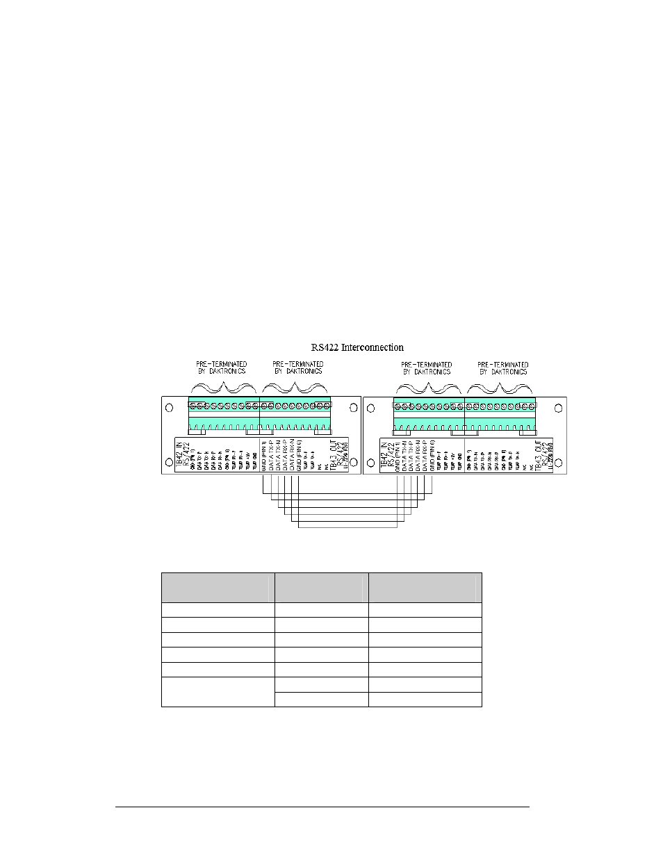
RS422 Interconnection
This is the most common method of terminating signal between two or more signs. A
6-conductor cable is used and one end terminates at the “OUT RS422” 10-position
terminal block (TB43) on the first display. The other end terminates at the “IN
RS422” 10-position terminal block (TB42) in the second display.
Figure 24: RS422 Interconnection
Sign A
Data Out (TB43)
Field Cabling
Sign B
Data In (TB42)
Pin 1 (GND)
Green
Pin 6 (GND)
Pin 2 (Data TX-N)
Blue
Pin 5 (Data RX-N)
Pin 3 (Data TX-P)
White
Pin 4 (Data RX-P)
Pin 4 (Data RX-N)
Brown
Pin 3 (Data TX-N)
Pin 5 (Data RX-P)
Black
Pin 2 (Data TX-P)
Red
Pin 1 (GND)
Pin 6 (GND)
Shield (Bare)
N.C.
Electrical Installation
3-12