Daktronics AF-3010-34 User Manual
Page 53
Reference Drawings:
System Riser Diagram; Power/Signal, V1500 Displays .............. Drawing A-88427
System Riser Diagram, RS422 ................................................... Drawing A-92681
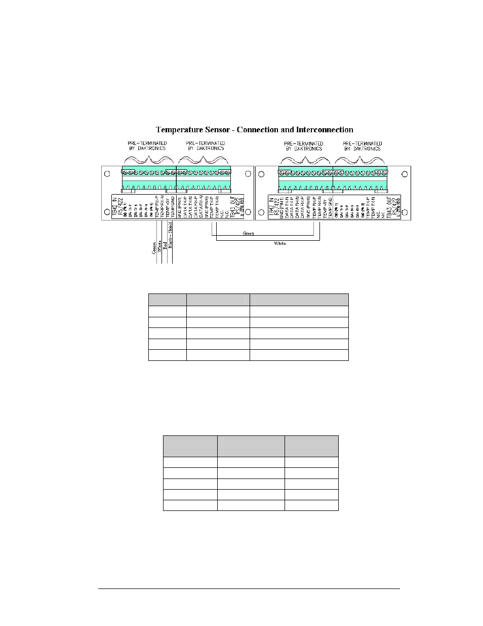
A 4-conductor cable with shield is used to connect the temperature sensor to the display. The
cable is terminated in the entrance enclosure on the terminal block labeled “TEMP SENSOR.”
Figure 36: Temperature Sensor--Connection and Interconnection
TB42
Cable Wires
Temperature Sensor
Pin 7
Green
Temp RX-P
Pin 8
White
Temp RX-N
Pin 9
Red
Temp +5V
Pin 10
Black
Temp GND
Pin 10
Bare
N/A
2V Displays
If the display is 2V, one temperature sensor is used for both sides. An extra piece of the 4-
conductor cable must be used to jumper the temperature sensor data to the second sign. Refer
to Drawing A-88426, Drawing A-88427, and Drawing A-92681 (located in Appendix C)
for connections. Note: Do not connect the red, black, or shield wires in the jumper to the
second sign. Refer to Figure 36 above.
Sign A
(TB43)
Field Cabling
Sign B
(TB42)
Pin 7
Green
Pin 7
Pin 8
White
Pin 8
NC Black NC
NC Red NC
NC Blue NC
A-2
Appendix A: Optional Temperature Sensor
- TI-3031 4-Inch LED Bar-Digit Locker Room Clock (22 pages)
- ST-2005 Backlit & Non-Backlit Scorer’s Tables (24 pages)
- BB-2135 Backboard LED Light Strip (36 pages)
- BB-2144 Tuff Sport Basketball LED Scoreboard (184 pages)
- TN-2563 Tuff Sport Indoor Multi-Court Tennis LED Scoreboard (112 pages)
- TN-2607 Single-Court Outdoor LED Tennis Scoreboard (134 pages)
- CR-2004 Multi-Section Cricket Scoreboard (90 pages)
- FT-7150 Touchpad (29 pages)
- SW-2008 Aquatics/Track LED Scoreboard (84 pages)
- SO-1424-11 Multi-Section Outdoor LED Scoreboard (158 pages)
- FB-4005-31 DistaView Outdoor LED Scoreboard (64 pages)
- MS-2018 Generation III Stackable LED Scoreboard (76 pages)
- GM-2103 LED Gymnastics Scoreboards (38 pages)
- HS-200 Horn Start (36 pages)
- Indoor Hockey Goal Lights (44 pages)
- LED End-of-Period Basketball Lighting (34 pages)
- MS-2013 Portable LED Scoreboard (52 pages)
- WR-2106 Matside Jr. LED Wrestling Scoreboard (44 pages)
- TI-2021 Multipurpose Track & Field LED Timing Display (50 pages)
- P1647 Multi-Section Outdoor LED Scoreboard (52 pages)
- P1647 Multi-Section Outdoor LED Scoreboard (50 pages)
- DA-1200 Outdoor Decorative Accent (30 pages)
- 2000 Rodeo OmniSport (72 pages)
- Outdoor LED Scoreboards Installation (58 pages)
- Outdoor LED Scoreboards Service Manual (52 pages)
- SO-2014 Generation IV Multi-Section Outdoor LED Scoreboard (208 pages)
- P1647 Multi-Section Outdoor LED Scoreboard (44 pages)
- PC-2001 Pace Clock System (40 pages)
- PC-2002 Pace Clock System (32 pages)
- BB-314 Portable LED Basketball Scoreboard (28 pages)
- Protective Screen (4 pages)
- TI-2002 Portable LED Timer (32 pages)
- Radar Gun Speed of Pitch Interface (27 pages)
- TI-2026 Segment Timer (28 pages)
- Single-Section Outdoor LED Scoreboards (46 pages)
- LED Aquatics/Track Displays SW-2000 Series 10 Numeric Digit (86 pages)
- TI-2022 Portable LED Timer (32 pages)
- Single Section DistaView Outdoor LED Scoreboards Generation IV (99 pages)
- BB-2151 (NBA only) Transparent Shot Clock (48 pages)
- TN-2563 Tuff Sport Indoor LED Tennis Scoreboard (34 pages)
- Scoreboard Trumpet Horn (50 pages)
- ST-3001 Tuff Sport & ColorSmart LED Scorer’s Table (48 pages)
- Tuff Sport & ColorSmart Indoor LED Scoreboards (46 pages)
- Tuff Sport Indoor LED Scoreboards (40 pages)
- Tuff Sport& ColorSmart FourSided Indoor LED Scoreboards (58 pages)