Controller board, Accessing and replacing the controller board, Leds and jumpers – Daktronics AF-3010-34 User Manual
Page 40: Controller board -4, Accessing and replacing the controller board -4, Leds and jumpers -4, Figure 28: controller board -4, Figure 29: leds and jumpers -4, 6 controller board
4.6 Controller
Board
Reference Drawings:
System Riser Diagram, RS422.......................................Drawing A-92681
Shop Drawing ........................................................... Refer to Appendix C
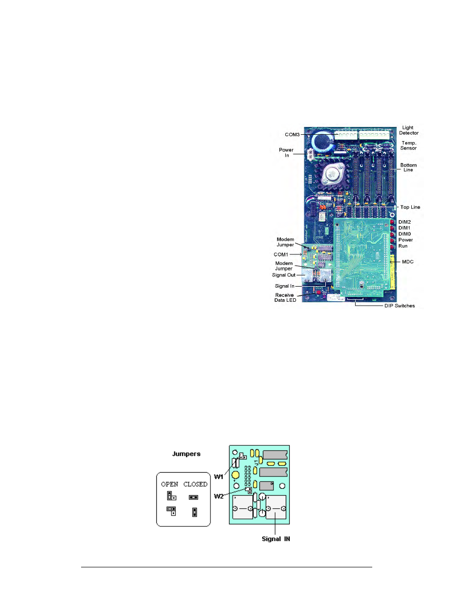
Figure 28: Controller Board
Accessing and Replacing the
Controller Board
The controller board is located behind the bottom,
left module (refer to shop drawings). To access
the controller board: Tools needed: 8mm Allen
wrench, 5/16" nut driver, and 3/16" nutdriver
1. Open the display and remove the module
in front of the controller board (refer to
Section 4.3 to remove a module).
2. Remove all power and signal
connections from the board. Pressing
outward on the tabs, and carefully
pulling them from the jack releases the
“Locked” connectors.
3. Remove the mounting six screws using a
3/16" nutdriver.
4. Carefully remove the controller board
from the display.
Follow the previous steps in reverse order to
install a new controller board.
LEDs and Jumpers
The controller board contains three DIM, one Power, one RUN, and one Receive
Data LEDs.
The controller’s communication module contains two (2) jumpers for a modem
system. The jumpers must connect both pins for a modem system. For all other
applications, the jumpers must be removed.
Figure 29: LEDs and Jumpers
Maintenance and Troubleshooting
4-4