Electrical installation, Electrical installation -2, Figure 3: lifting the display -2 – Daktronics DF-1060 User Manual
Page 14: 2 electrical installation
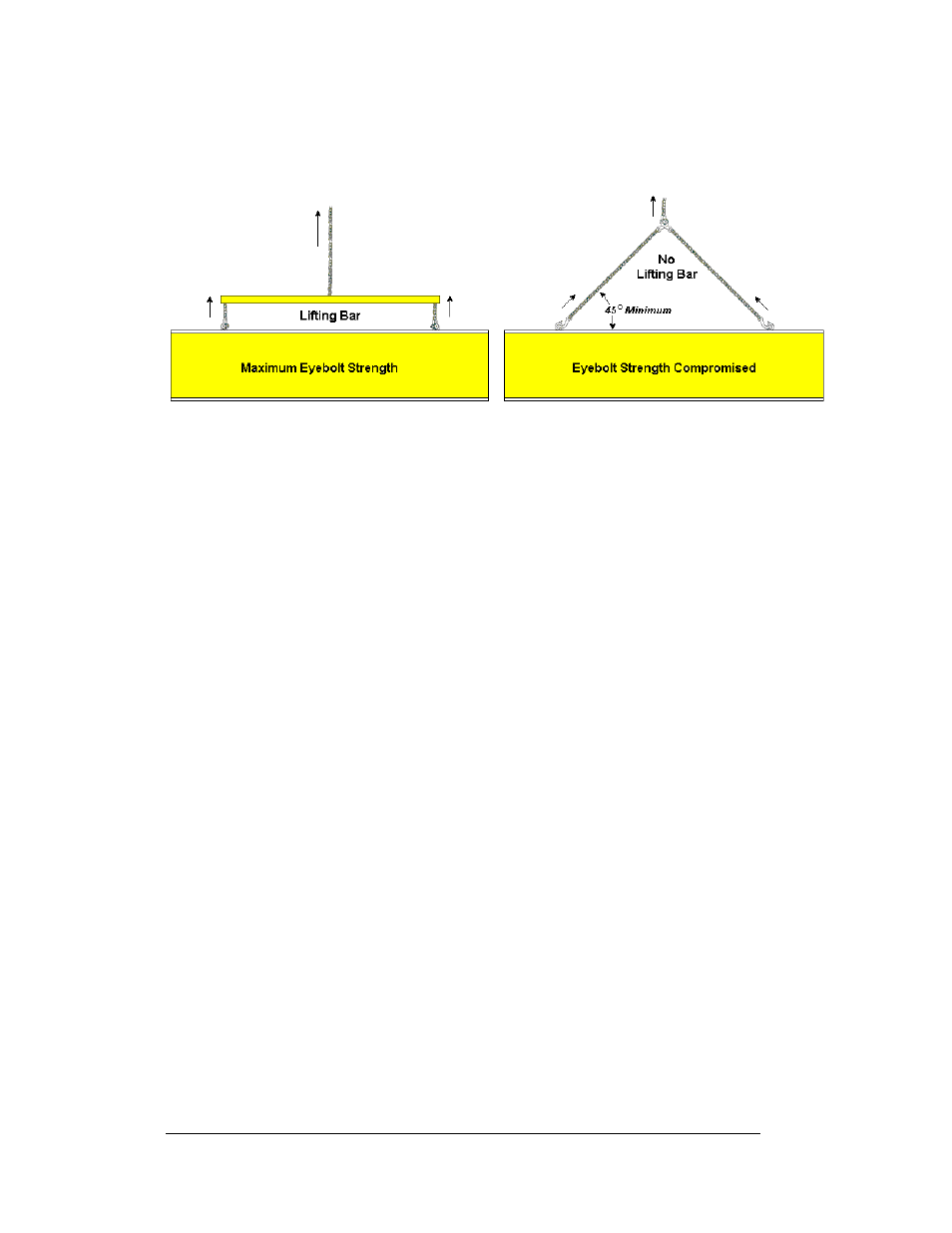
Figure 3, below, illustrates two lifting methods. The illustration shows both the
preferred method (left example) and an alternative method (right example) for lifting
a display. Be sure to use every lifting point provided.
Figure 3: Lifting the Display
Eyebolts are intended for lifting during installation only. Do not attempt to
permanently support the display by the eyebolts.
Note: Daktronics assumes no liability for display damage resulting from incorrect
setup or incorrect lifting methods.
In installations in which an ad panel or some other display section may be added to
the base display, the lower section is installed first and secured to the support beams,
and then the upper section is placed atop or above the lower sign section and
attached to the beams. There may be cables extending from the top of the lower
section. Guide these cables into the hole in the bottom of the upper section for later
connection.
Installers may remove the lift eyebolts once the display is in place. Inspect the top
and sides of the display for any holes or openings that may allow moisture to enter
the display, and plug and seal those openings with silicone or another waterproofing
sealant.
2.2 Electrical
installation
Electrical installation consists of the following processes:
Providing power and ground to a disconnect near the display.
Routing power and ground from the main disconnect to the display
driver/power enclosure.
Connecting the display ground to a grounding electrode at the sign location.
Routing the control signal cable from the control location to the sign
location.
Note: Only qualified individuals should perform power routing and termination to
the display. It is the responsibility of the electrical contractor to ensure that all
electrical work meets or exceeds local and national codes.
2-2
Mechanical and Electrical
Specifications