Module and power supply diagnostics, Module self-test, 4 module and power supply diagnostics – Daktronics Rear-Ventilated GalaxyPro GP3 Series User Manual
Page 33
28
Display Troubleshooting
Code
Description
8
8
8
Testing 7 segments (held for 2 seconds)
t
s
t
Initial test in progress (60-second duration)
P
A
S
All tests passed
E
r
r
Test failures reported
F
0
1
Fiber Port A Error
F
0
2
Fiber Port B Error
F
0
3
RJ45 IN (Port A) Error
F
0
4
RJ45 OUT (Port B) Error
F
0
5
ProLink5 (SATA) Port A Error
F
0
6
ProLink5 (SATA) Port B Error
If any Err message is displayed, send the PLR back to Daktronics for repair or replacement.
11.4 Module and Power Supply Diagnostics
Each module in a GalaxyPro
®
GP3 display has a power supply attached to it. Each power supply
provides power only to the module it is connected to. Display modules are equipped with a
status indicator LED that can help troubleshoot possible issues. Under normal operation, the
status indicator LED should flash once every 4 seconds.
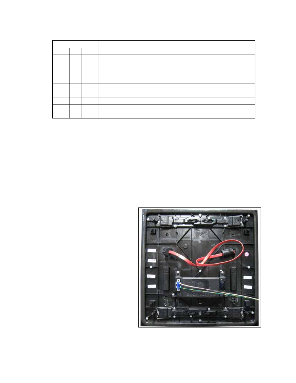
Module Self-Test
If a module is blank, but has power supplied to it, perform a module self-test to diagnose a
module or SATA cable failure. To perform a self-test, follow the steps below.
1. Attach a SATA cable to Port A
and Port B on the module, as
2. Disconnect the power to the
power supply for 10 seconds.
3. Reconnect the power to start
the self-test.
4. Verify the module is running a
self-test.
Remove the SATA cable and cycle
power to the module to stop the self-
test.
Figure 26: Module Self-Test