Earth ground installation, 2 earth ground installation – Daktronics Rear-Ventilated GalaxyPro GP3 Series User Manual
Page 15
10
Electrical Installation
7. Connect power line 1 (L1) to the appropriate tap (black tape on cable).
8. Connect power line 2 (L2) to the appropriate tap (red tape on cable).
9. Connect the neutral to the appropriate tap (white tape on cable).
10. Reinstall the power enclosure cover using all four screws.
5.2 Earth Ground Installation
Daktronics GalaxyPro
®
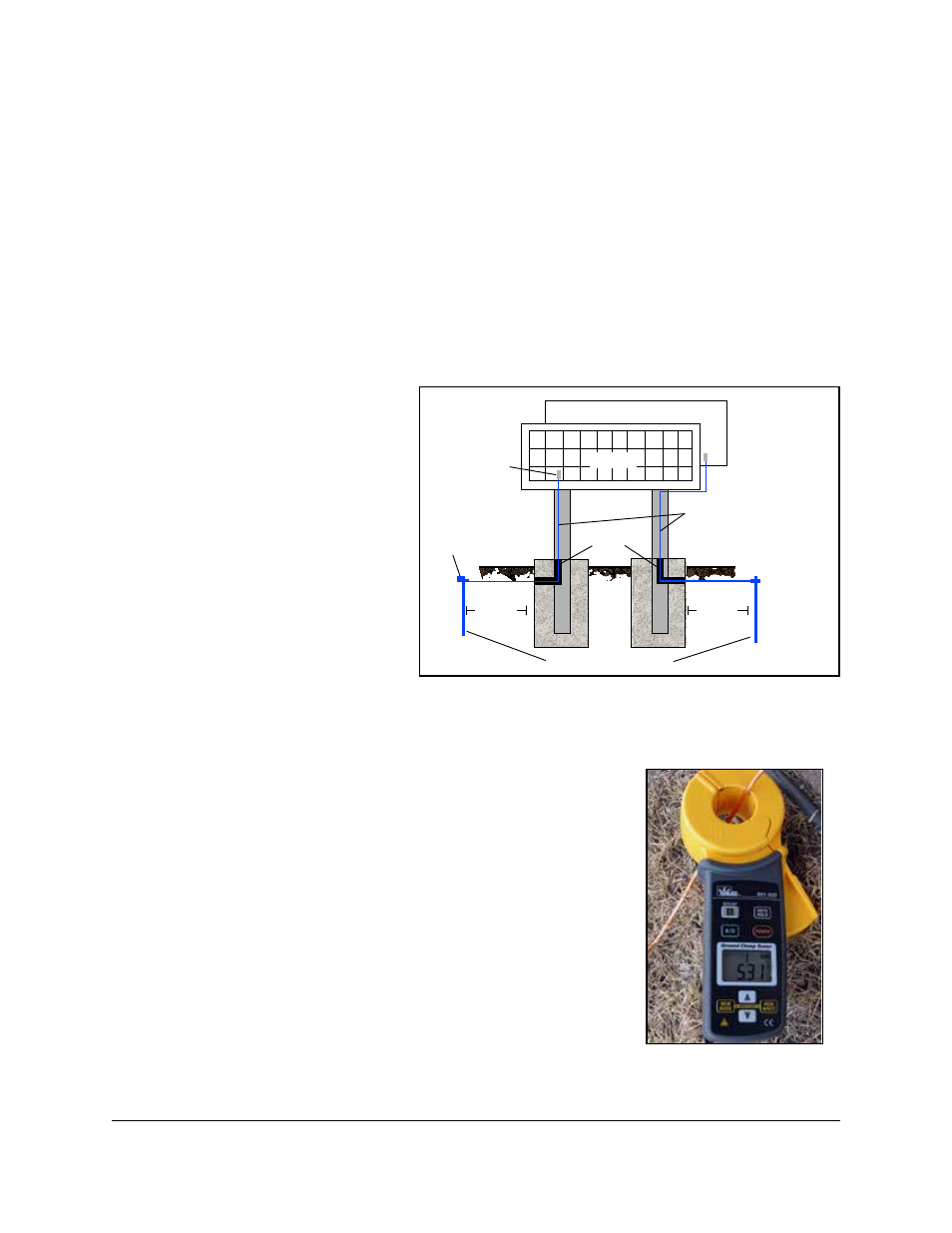
GP3 displays require a resistance to ground of 10 ohms or less. Follow the
steps below to connect the display to an earth-ground electrode and measure the resistance to
ground.
1. Install an earth-ground
electrode (ground rod,
ground plate, etc.) near the
base of the display. Refer
to Figure 11 for guidelines.
Note: Each display face
requires an earth-ground
electrode.
2. Connect a copper wire
from the grounding
electrode to the ground
lug on the back of the
display.
3. Using an Earth Ground Clamp Meter, shown in Figure 12, measure the resistance to
ground near the grounding electrode. If the reading is greater than 10 ohms, install
additional grounding electrodes.
4. Bury any copper cable or grounding electrodes so they are
below grade.
Important points about grounding:
• Follow local and national codes: The material of an earth-
ground electrode differs from region to region and from
conditions present at site. Consult any electrical codes that
apply.
• Support structure cannot be used as an earth-ground
electrode: The support structure is generally embedded
in concrete, and if embedded in earth, the steel is either
primed or it corrodes, making it a poor ground.
• One grounding electrode for each display face
Primary
Mirror
Display
Ground Lug
Thermal Weld
Connection
Preferred
Conduit
Copper Ground Conductor
(One Per Display Face)
Copper Ground Rods
8 ft.(2.5 m)
min.
8 ft.(2.5 m)
min.
Figure 11: Proper Display Grounding
Figure 12: Measure
Resistance to Ground