Section 11, Display troubleshooting, Power and signal routing – Daktronics Rear-Ventilated GalaxyPro GP3 Series User Manual
Page 30: Power routing, Figure 22, 1 power and signal routing
25
Display Troubleshooting
Section 11: Display Troubleshooting
This section provides basic display information such as power and signal routing as well as basic
troubleshooting tips for common problems. For issues not addressed in this manual, please contact
Daktronics Technical Support.
11.1 Power and Signal Routing
Understanding power
and signal flow through
the display can help a
technician troubleshoot
an issue.
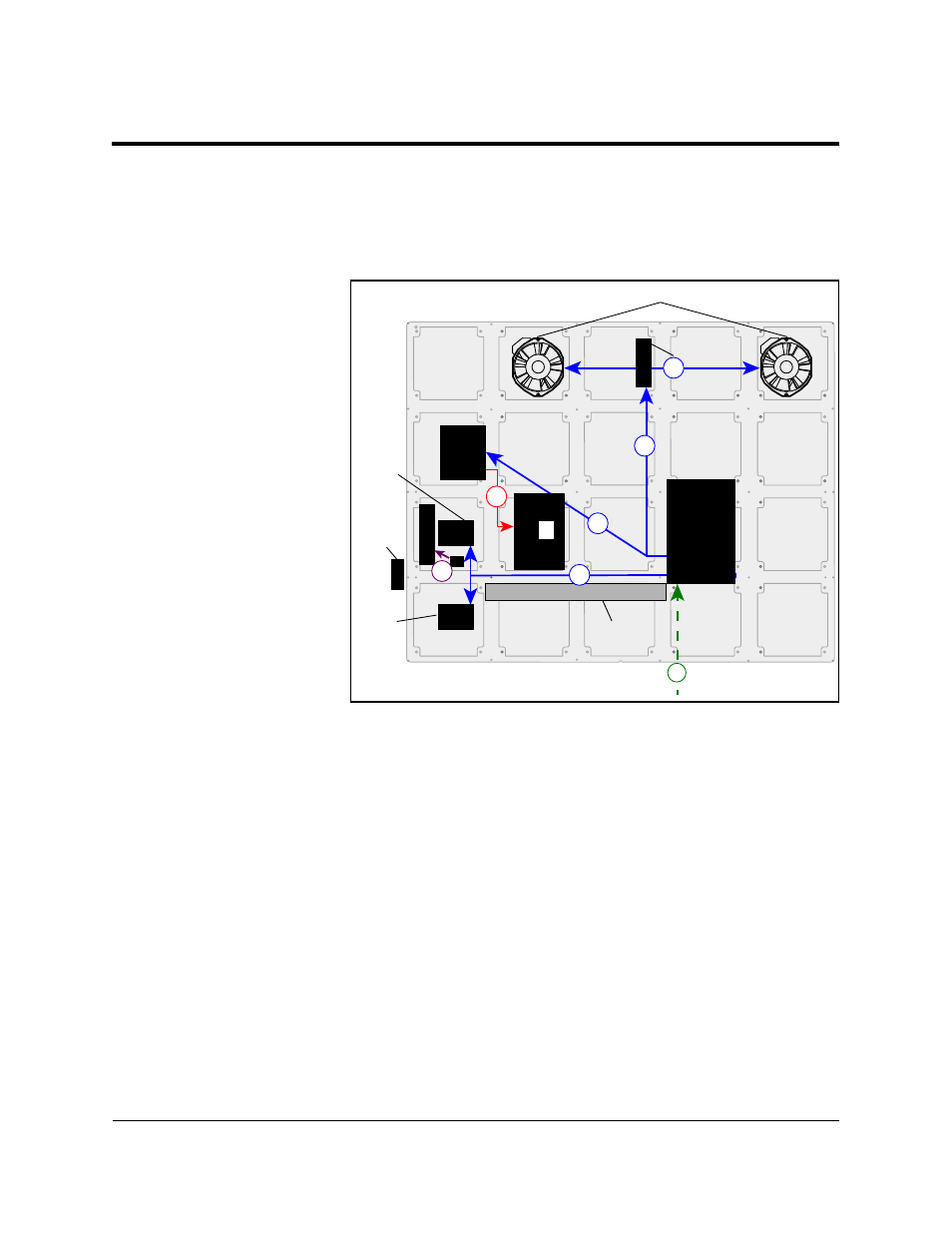
Power Routing
Figure 22 shows how
power is routed through
the display.
1. AC Power enters
the display
through the
power entrance
box on the back
of the display
and travels
to the Power
Termination
Panel.
2. Power is
distributed to Module Power Supplies (2a), Player Power Supply (2b), Thermostat (2c),
and Fans (2d).
Note: Each module has its own Module Power Supply attached to the back of the
module.
3. DC Power is supplied to the Player (3) from the Player Power Supply.
4. DC Power is also supplied to the PLR (4) from the PLR power jack on the back of the
module.
Thermostat
Fans
Module
Power
Supply
Light
Sensor
Module
Power
Supply
(one on
every
module)
Filter
P
LR
Player
Enclosure
Power
Termination
Panel
Player
Power
Supply
2a
1
2b
2c
4
3
2d
Figure 22: Power Routing