Player diagnostics, Plr diagnostics, Plr self-test – Daktronics Rear-Ventilated GalaxyPro GP3 Series User Manual
Page 32: 2 player diagnostics, 3 plr diagnostics
27
Display Troubleshooting
11.2 Player Diagnostics
DMP-4060 is the player in a
GalaxyPro
®
GP3 display. The
player is located in the lower-
left portion of the display in an
environmental enclosure. The
player receives incoming signal
from the control computer and
routes that signal to the ProLink
Router (PLR). The player has
several LEDs on it that can be
useful when troubleshooting a
communication issue. Figure 24
explains those LEDs.
11.3 PLR Diagnostics
The ProLink Router (PLR),
receives signal from the display
player, which transfers it on
to the modules through SATA
cables. GalaxyPro
®
GP3 displays
are equipped with a redundant
signal path, meaning two SATA
cables are connected to each
module. If one of the two SATA
cables fail, the module continues
to receive data from the other SATA cable and the display continues functioning normally.
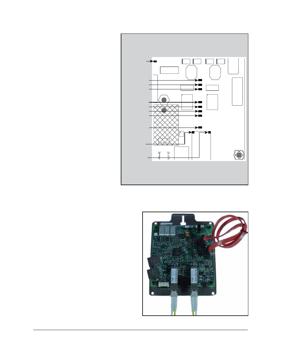
PLR Self-Test
When put into self-test mode, the PLR tests
for correct operation and displays pass/fail
status on the 7-segment display.
To put the PLR into self-test mode, loop a
SATA cable between ports A and B. Then
take a fiber cable and connect the fiber
ports together, as shown in Figure 25. Once
the cables are connected, cycle power to
the PLR and it will boot-up in self-test
mode. Following is a table of a few possible
messages. Contact Daktronics Technical
Support for additional information or
questions.
1 2
3
4
5
678
C
D
EF
9A
B
0
1 2
3
4
5
678
C
D
EF
9A
B
0
INDICATORS
RUN-Flashes
during
operation
ETH0 1000MB
ETH0 100MB
ETH0 10MB
ETH0-ON
Full Duplex
ETH1 1000MB
ETH1 100MB
ETH1 10MB
ETH1-ON
Full Duplex
ETHERNET
Hardware link
flashes during
TX comm.
Flashes during
RX comm.
Figure 24: Controller Diagnostic LEDs
Figure 25: PLR Self-Test Setup