Signal routing – Daktronics Rear-Ventilated GalaxyPro GP3 Series User Manual
Page 31
26
Display Troubleshooting
Signal Routing
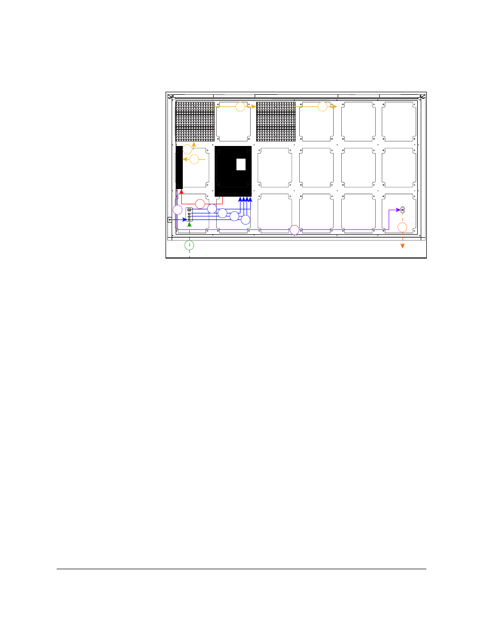
Figure 23 shows how signal is routed through the display.
1. Signal enters
the display
from the
external
signal
enclosure
through
the signal
input quick-
connect jacks
(1).
2. Signal travels
from the J32
signal input
jack through
an Ethernet
Cat5e cable
to the J32
Ethernet jack on the player (2a)
• The J33 auxiliary input jack is connected to the J33 jack on the player (2b).
• The temperature sensor is connected to the J31 input quick-connect jack. From
the J31 quick-connect jack it is connected to the J31 jack on the player (2c).
• The light sensor is connected to the J35 input quick-connect jack. From the J35
quick-connect jack it is connected the J35 jack on the player (2d).
3. Signal travels from the player from Fiber A to the PLR Port A (3).
4. From SATA A on the PLR, signal goes to the first module (4a) and travels from module
to module via SATA cables (4b), finally returning to the PLR to SATA B (4c).
5. Signal leaves the PLR from Fiber B and travels to the Output Fiber Quick Connect (5).
6. Signal from the primary display face Output Fiber Quick Connect travels to the mirror
face (6) to jack J32.
1
2a 2b
3
4a
5
4b
4b
6
2c 2d
5
4c
Figure 23: Signal Routing