Section 3, Display installation, 1 display installation – Daktronics Rear-Ventilated GalaxyPro GP3 Series User Manual
Page 10
5
Display Installation
Section 3: Display Installation
This section explains the steps necessary for proper lifting and installation of the display to the sign
structure.
Follow all guidelines and safety precautions in this manual when installing the display.
Do not modify the display or control system in any manner without the written permission of Daktronics’
engineering staff. Any unauthorized modifications will nullify the warranty.
Display Installation Dos
• Inspect the display for damage prior to installation
• Use all T-clips for mounting
• Provide an adequate support structure that is straight and level
• Provide adequate ventilation that meets or exceeds display specifications.
Note: Shrouding may be used, but proper ventilation must be placed into the shrouding.
• Use all lift eyes when lifting the display
• Install all splice plates and splice T-clips when applicable
Display Installation Don’ts
• Drill holes into the display
• Block display ventilation system
• Use the lift eyes for display mounting
• Move clip angles outside the designated zones indicated by label
3.1 Display Installation
1. Use a utility knife to
carefully cut away all
of the white packaging
material from the display.
Be careful not to damage
the face of the display or
LEDs.
2. If the display is multi-
sectional, refer to Section
4 before continuing.
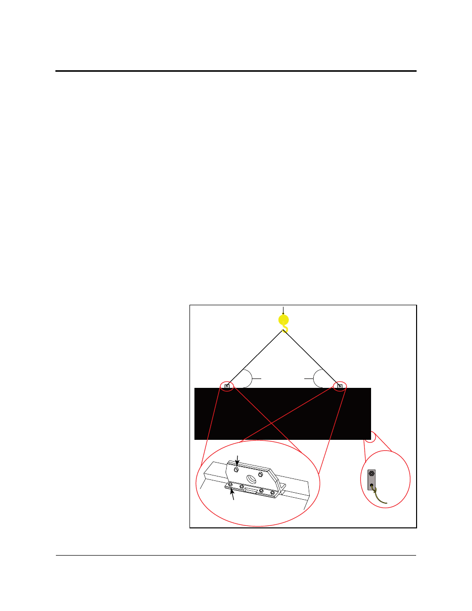
3. Attach a crane or lift
truck to the lift eyes on
the display’s top.
Note: Lift eye spacing
is set at Daktronics and
should not be moved.
Lift eyes should also
remain in place after
installation is complete.
Figure 2: Proper Display Lifting
From Back
Tag Line
Tie Off
Angle must be
greater than 55°
Lift-Eye Bolts
Set Bolts