System operation, Overview, Chapter 3. system operation – Comtech EF Data DT-4500 Series User Manual
Page 43: Verview, Figure 10. rear panel (with rsm module)
25
Chapter 3. System Operation
3.1 O
VERVIEW
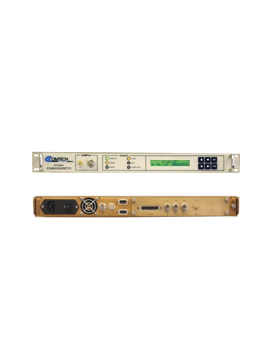
This chapter contains instructions for operating the converter. Illustrations of the front
and rear panels are provided showing the keypad for operator input commands, LCD
Display, LED status indicators, and the connectors. Tables are provided to show the
control and operating functions of the converter.
The front and rear panels are shown below. Table 12 lists of the operating functions for
the keypad, LCD display, LED indicators and test sample connections on the front panel.
Figure 9. Front Panel (Model DT-4511 shown)
J4
J6
J8
J5
RF
LP OUT
LP IN
IF
J3 HSB
P1 RELAY
J1 COM 1
EXT REF
J2B OUT
EXT REF
J2A IN
MA
DE I
N
USA
Figure 10. Rear Panel (with RSM Module)
This manual is related to the following products: