Comtech EF Data CiLink User Manual
Page 29
CSAT-5060/XSAT-7080 Transceiver iPAQ Link
Revision 2
Operations
MN/CiLink.IOM
3–7
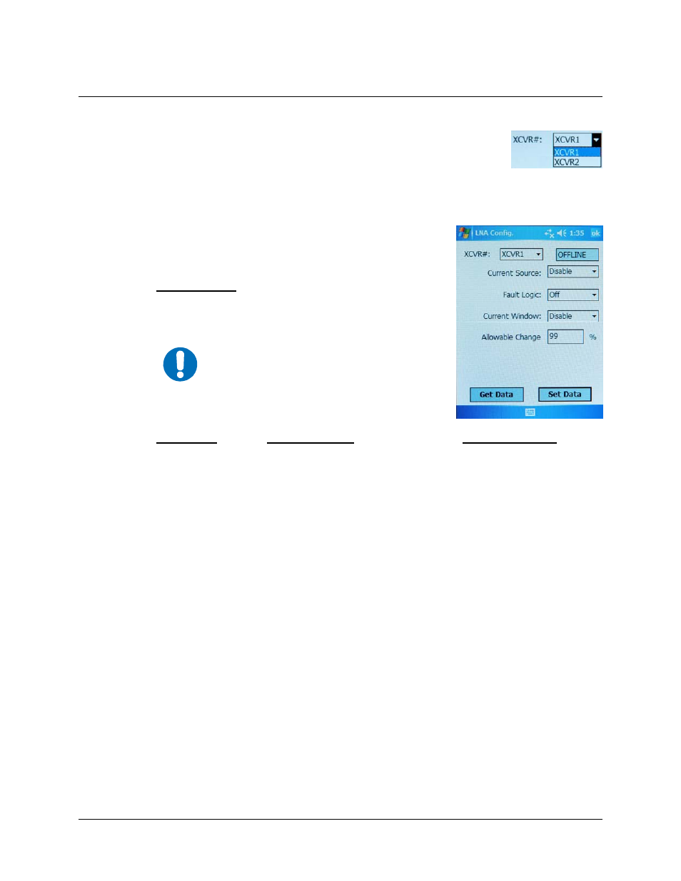
3.3.2.3 Main Menu
Æ Configuration Æ LNA (Low Noise Amplifier)
The currently selected transceiver is the unit that will be polled for status
information in the LNA configuration XCVR# selection box:
XCVR1
is the default selection and
XCVR2
is not selectable if CiLink is set to operate under standalone
(non-redundant) system parameters (see
Configuration
Æ
System Type
for detailed information).
The status-only
ONLINE/OFFLINE
field located to the right of the
XCVR#
selection box indicates the active line status of the
currently selected transceiver.
• Current Source [Enable/Disable]
▼ – The transceiver has
the circuitry to source up to 400 mA of current at 12 VDC
to power an LNA.
• Fault Logic [On/Off] Current Window [Enable/Disable]
▼,
Allowable Change
– When
the transceiver has been configured to supply current to the LNA (refer to
Current
Source
on this page) adjustable LNA current monitoring is available.
Setting the
Fault Logic
to
On
or
Off
allows the user to control whether or not the
redundancy controller switches on an LNA current alarm in the redundant configuration.
The transceiver allows the user to select whether or not the summary fault relay is activated
if the LNA current moves out of a prescribed window.
The alarm is configured by attaching the LNA, turning on the current source,
enabling
the
Current Window
, then setting the
Fault Logic
to
On
. Then, the
Allowable Change
feature permits the user to ‘calibrate’ the current and define an operational range window,
specifying a current usage percentage value of anywhere from ± 20% to ± 50% to trigger
an alarm.
The user can disable this ‘window detect’ feature by setting the window value to ± 99%.
Tap
[Set Data]
to
save
the updated configuration selections. Otherwise, tap
[ok]
to
return
to the
Main Menu
from the
Configuration
Æ LNA
screen without saving any changes.
IMPORTANT
Care should be taken when directly
connecting the transceiver to lab test
equipment – a DC block should be used
between the "RF IN" port and the RF test
source to protect the test equipment in
case the source is accidentally turned on.