3 transceiver cable connection – Comtech EF Data CiLink User Manual
Page 19
CSAT-5060/XSAT-7080 Transceiver iPAQ Link
Revision 2
Setup
MN/CiLink.IOM
2–3
IMPORTANT
Throughout this manual, ‘transceiver’ and ‘XCVR’ are used interchangeably to
refer to the CSAT-5060 or XSAT-7080 interface.
2.3
Transceiver Cable Connection
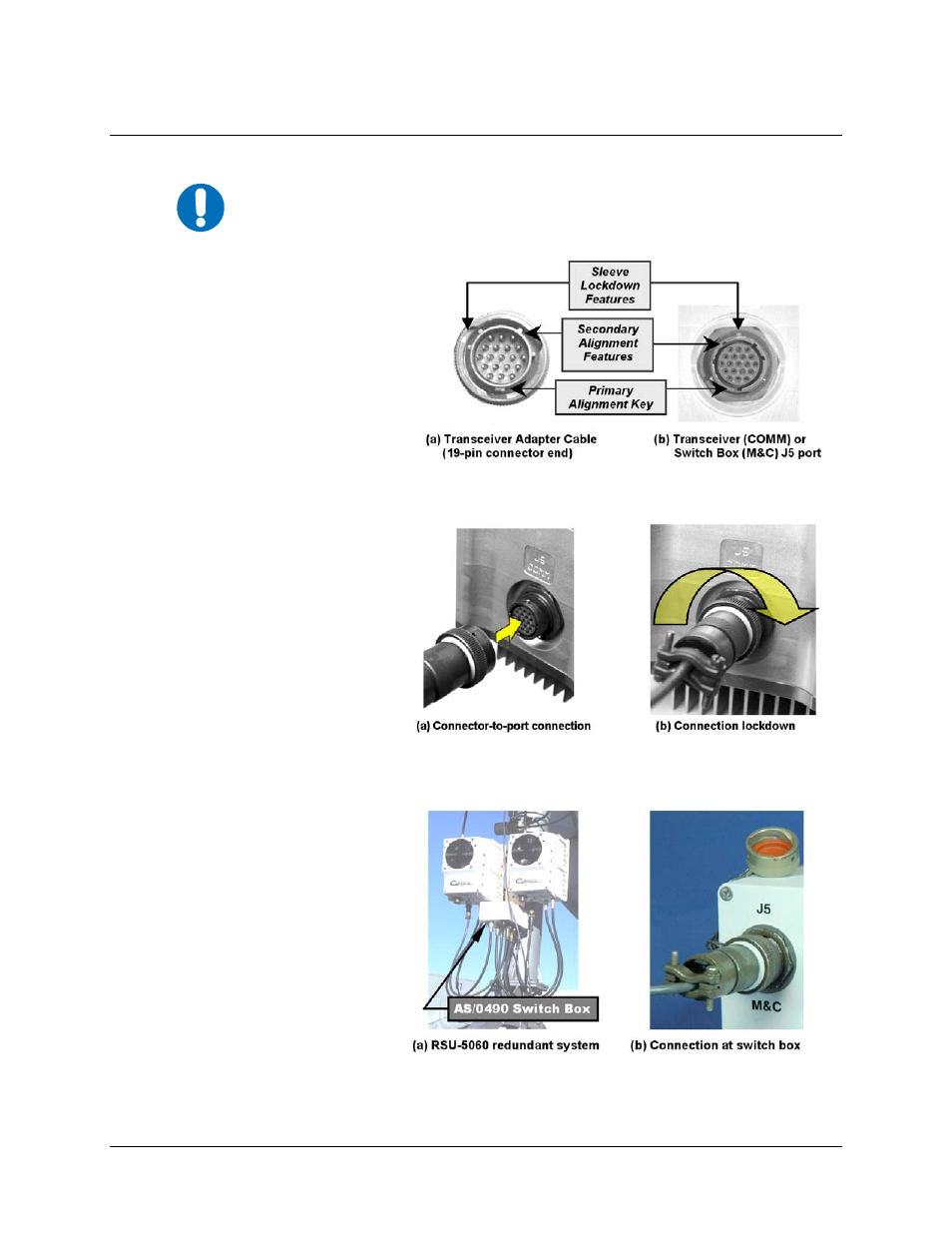
Figure 2-4. 19-pin Connector Key Alignment
Transceiver Adapter Cable connection to J5 COMM port
Figure 2-5. Transceiver Connection
Transceiver Adapter Cable connection to J5 COMM port
Figure 2-6. RSU-5060 Redundant System Connection
Transceiver Adapter Cable connection to J5 M&C port at the
AS/0490 switch box
Figures 2-4 through 2-6 depict
connection of the Transceiver
Adapter Cable 19-pin connector
end to the J5 COMM port at
either a standalone transceiver
or at the AS/0490 switch box
used in an RSU-5060 redundant
installation [see Figure 2-6].
For either connection, the J5
COMM port features a keyed
configuration [see Figures 2-4(a)
and 2-4(b)].
Engage the primary alignment
key, then plug the connector
into the J5 port by pushing the
connector forward to engage
both the alignment key and the
secondary keyed tabs [see
Figure 2-5(a)].
Complete the connection by
turning the connector sleeve
clockwise until the sleeve
lockdown tabs engage fully
with an audible ‘click’ [see
Figure 2-5(b)].