C.5 logic control assembly – Comtech EF Data RC-1160 User Manual
Page 64
Theory of Operation
Revision 1
RC-1160 RC-1260 Redundancy Switch Controllers
MN-RC1160RC1260
C-4
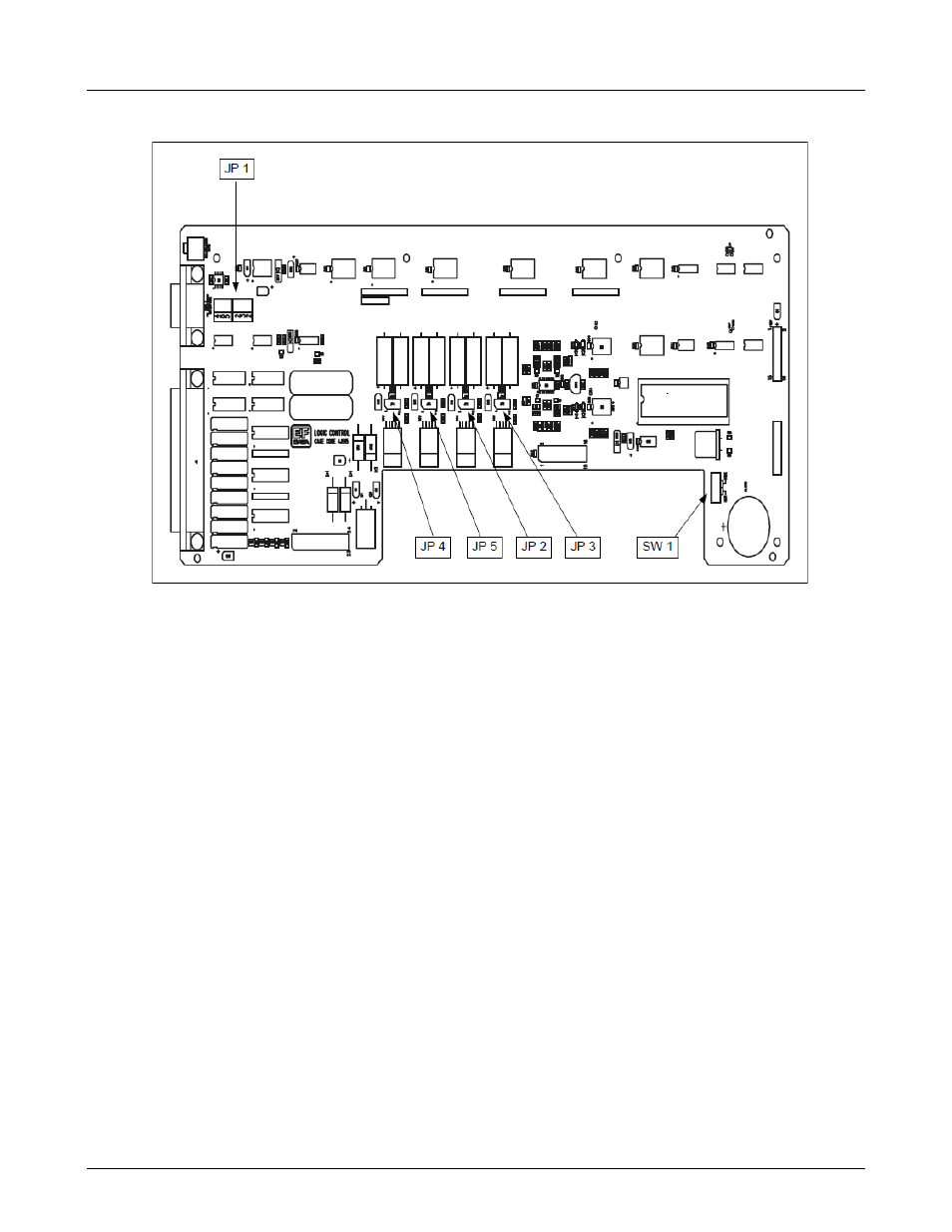
C.5 Logic Control Assembly
Figure C-2. Logic Control Board Assembly
The Logic Control Assembly (Figure C-2) creates the necessary voltages to allow the system to operate
properly. Voltages include:
•
• +13V for all LEDs and relays
•
• +5V for the CMOS/TTL logic
•
• 11V for the EIA-232 serial interface
Analog/Digital (A/D) converters U8 and U9 monitor the input voltages directly from the power supplies. The
A/D converters produce a fault if either voltage drops below 13V.
Microcontroller U16, 87C51 cycles in one of two repetitive loops, depending on whether the unit is in auto or
manual mode. The microcontroller constantly monitors the required inputs.
•
In Manual mode, the switch command inputs are observed.
•
In Auto mode, the faults are observed, analyzed, and the necessary configuration changes are
implemented.
If the microcontroller jumps out of one of the designated loops and hangs up, the watch dog timer will time-out
in approximately 5 seconds. The watch dog timer will then reset the microcontroller, thus re-initializing the unit.
This initialization is identical to the power up which places the unit in the last configuration it was in before
power was turned Off.
The microcontroller monitors the LNA/LNB voltage from the AC/DC power supply, and the wave guide switch
DC voltage (DC systems only), from the wave guide switch power output. If either voltage is missing or too
low, the corresponding PS1 or PS2 front panel LED will be turned Off.