4 lna, lnb, and waveguide pinouts – Comtech EF Data RC-1160 User Manual
Page 30
Installation
Revision 1
RC-1160 RC-1260 Redundancy Switch Controllers
MN-RC1160RC1260
2–8
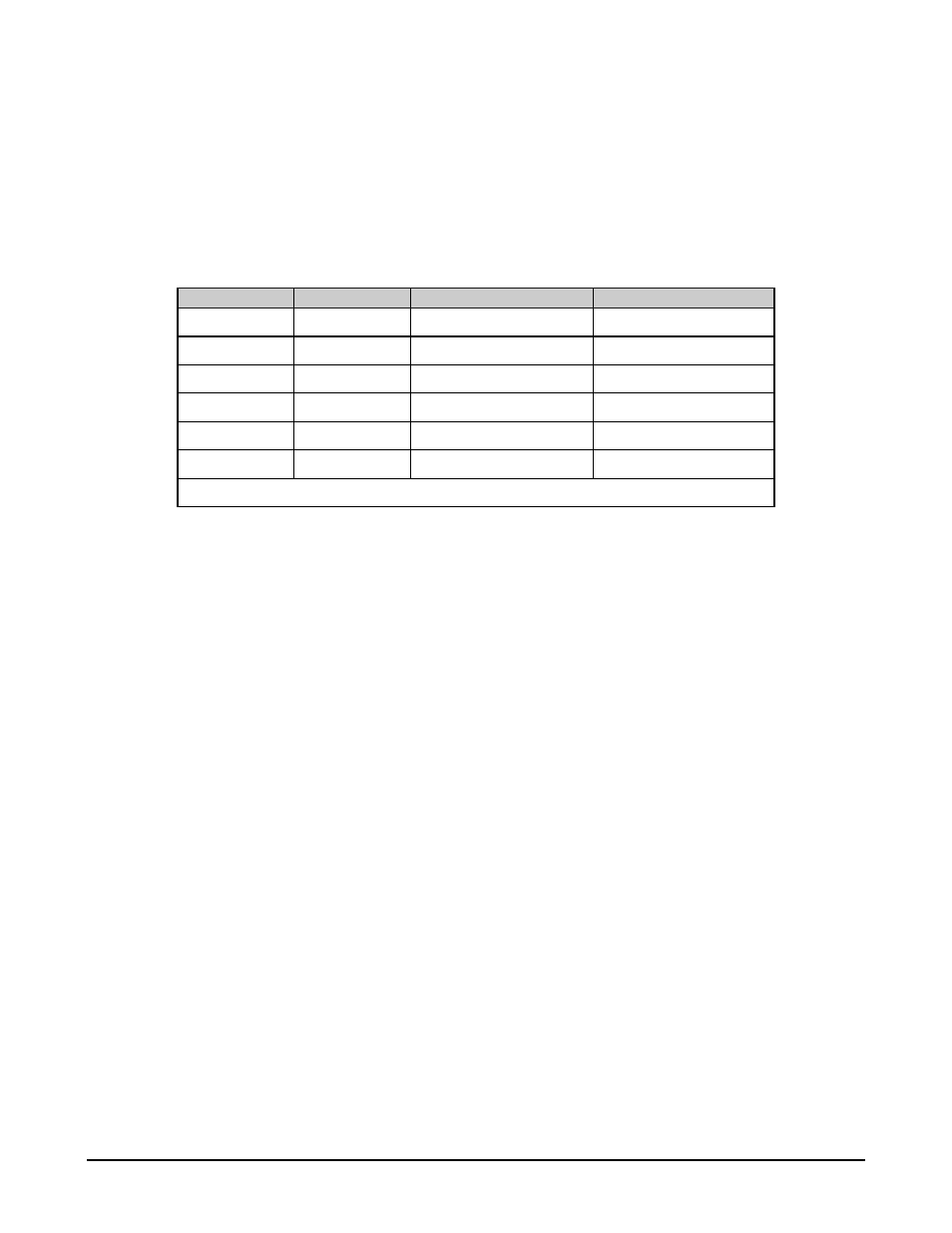
2.4.4 LNA, LNB, and Waveguide Pinouts
LNAs and LNBs can be supplied with three different connector configurations, depending on the model and
options. The most common LNA/LNB pinouts are 3-, 4- and 6-pin.
Waveguide connectors are always 6-pin, but vary in size, depending on the frequency of the switch (C-band, X-
band, S-band, and Ku-band). See Table 2-4 for pinouts of the above connectors.
Table 2-4. LNA, LNB, and Waveguide Pinouts
3-Pin LNA/LNB 4-Pin LNA/LNB
6-Pin LNA/LNB
Waveguide Switch
A Power Input A Power Input A power input
A Position 1, Command
B GND
B (See Note) B GND
B Command, Common
C GND
C GND
C FLT, normally closed C Position 2, Command
D GND
D FLT, common
D Indicator, Position 1
E FLT, normally opened E Indicator, Common
F N/C
F Indicator, Position 2
Note: This pin is reserved for oven voltage.