Comtech EF Data OMS11 User Manual
Page 58
OMS11 1:1 Redundancy Switch
Appendix A
TM133 – Rev. 1.1
A-
1
OMS11 DIP Switch Configuration
A
The OMS11 has four internal DIP switches that are accessible only by removing the top cover.
These DIP switches S2, S3, S4 & S5 are used to configure Interface options, data rates and
remote baud rates. An upgrade or change from an existing interface or configuration to another
may require a change to one or more of the DIP switch settings. If you are having trouble with
DIP switch settings, contact Radyne Customer Service for any additional help.
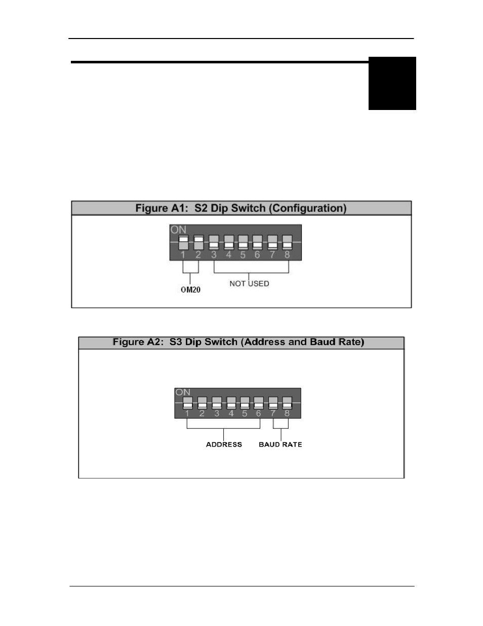
Figure A-1 Illustrates the DIP switch positions for the OM20.
Figure A-2 Illustrates the unit Addressing for and Baud Rate switch positions for remote M&C.
Figure A-1. DIP Switch Positions for the OM20
Figure A2. DIP Switch showing Address and Baud Rate
Table A-1 identifies the various S3 dip switch positions. Pins 1 - 6 are utilized for M&C unit
addressing when using multiple switches. Pins 7 & 8 are utilized for baud rate for the terminal or
remote M&C. Address settings are also accessible through the Remote Port (J-20) with the
switch in Terminal Mode. An empty space in Table A-1: represents the (off) position.