Connector pinouts – Comtech EF Data OMS11 User Manual
Page 34
OMS11 1:1 Redundancy Switch
Connector Pinouts
TM133 – Rev. 1.1
5-1
Connector Pinouts
5
5.0
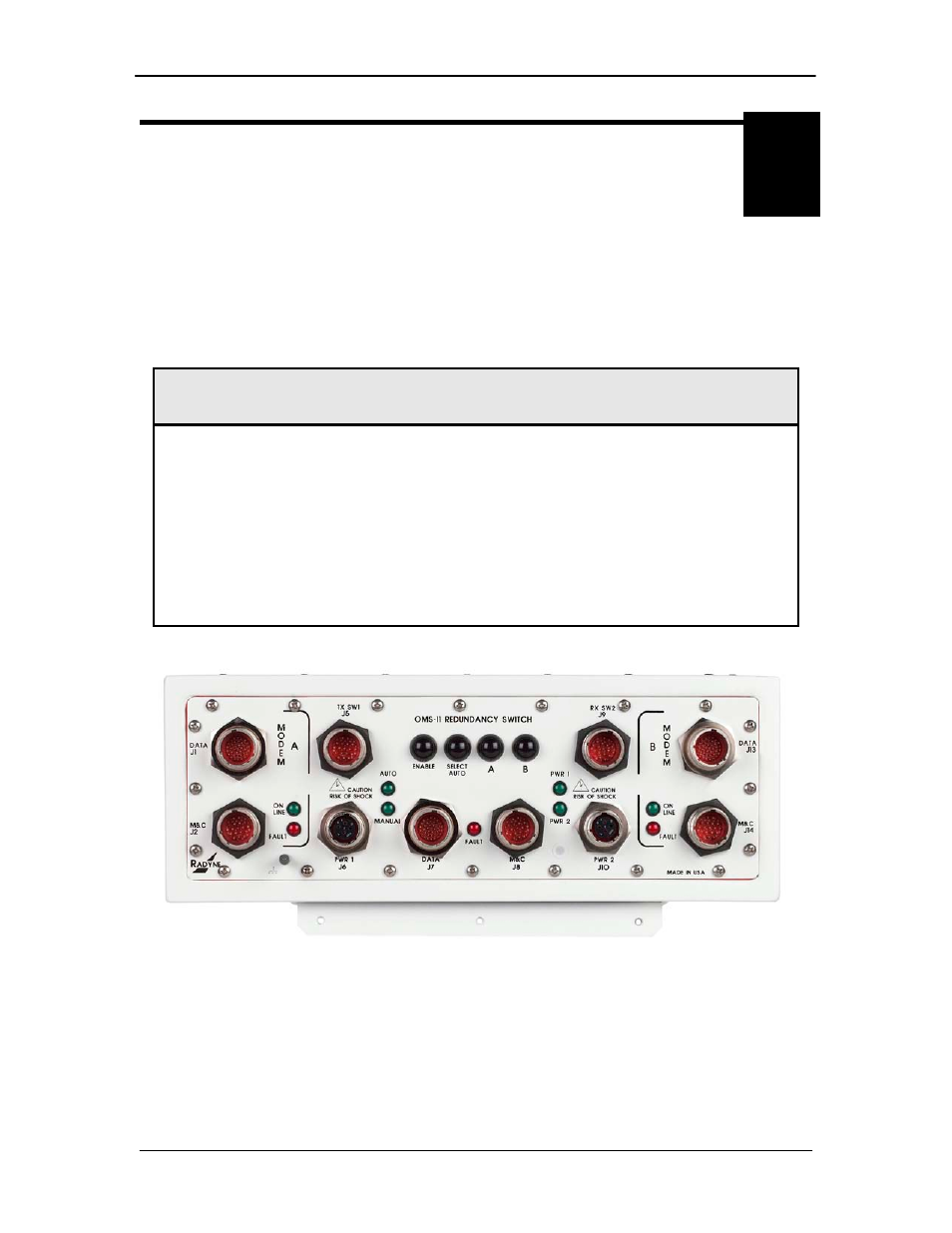
OMS11 External Interface Connections
All OMS11 external connections are interconnected to labeled connectors located on the front of
the unit. Any connection interfacing to the OMS11 must utilize the appropriate mating connector
(supplied). Refer to Table 5-1. OMS11 Connections and Figure 5-1. OMS11 Connection Ports
for the standard unit. Reference throughout this section will be identified as the OMS11.
Table 5-1. OMS11 Connections
Connector
Label
Description
Location
J1
DATA A
RS422 Data I/O / G.703 Balanced / Async
MODEM A
J2
M&C A
RS485 Monitor & Control
MODEM A
J5
TX SW1
TX Waveguide I/O, 48V
OMS11
J6
PWR 1
Power
OMS11
J7
DATA
RS422 Data I/O / G.703 Balanced / Async
OMS11
J8
M&C
RS232/RS485 Monitor & Control
OMS11
J9
RX SW2
RX Waveguide I/O, 48V
OMS11
J10
PWR 2
Power
OMS11
J13
DATA B
RS422 Data I/O / G.703 Balanced / Async
MODEM B
J14
M&C B
RS485 Monitor & Control
MODEM B
Figure 5-1. OMS11 Connection Ports