Comtech EF Data OMS11 User Manual
Page 44
OMS11 1:1 Redundancy Switch
Connector Pinouts
TM133 – Rev. 1.1
5-11
5.7
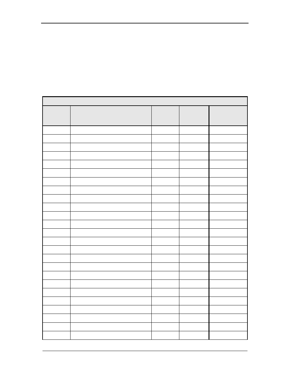
Modem B Data Interface (J13) – RS422 Synchronous Data,
Asynchronous Overhead Data, and G.703
Balanced Data I/O Port
This 38 Pin D38999/24FD35PN Connector contains the RS422 data connections, RS485
Asynchronous Overhead data interface; G.703 Balanced interface, and the Open Collector
Modulator and Demodulator Faults. Refer to Table 5-10 for pin-outs. Refer to Table 5-11 for
G.703 pin-outs.
NOTE: Data cables between the Modem and OMS11 are different based on interface type:
G703 Balanced
CAR5902
RS422
CAR5918
Table 5-10 RS422 Synchronous Data I/O; Async Data Connector (J13)
J13
Pin No.
RS422 - Signal Name
Signal
Direction
EIA-530 Std.
25 Pin
Reference
1
Shield--- ---
1
2
Send Data B (+)
SD-B
Input
14
3
Send Data A (-)
SD-A
Input
2
4
Send Timing A (-)
ST-A
Output
15
5
Receive Data
RD-A
Output
3
6
Receive Data B (+)
RD-B
Output
16
7
Request To Send A (-)
RS-A
Input
4
8
Receive Timing A (-)
RT-A
Output
17
9
Clear To Send A (-)
CS-A
Output
5
10
Modulator Fault – Open Collector
MF
Output
18
11
Data Mode A (-)
DM-A
Output
6
12
Request To Send B (+)
RS-B
Input
19
13
Signal Ground
SGND
---
7
14
Data Terminal Ready A (-)
TR-A
Input
20
15
Receiver Ready A (-)
RR-A
Output
8
16
Demodulator Fault
DF
Output
21
17
Receive Timing B (+)
RT-B
Output
9
18
Data Mode B (+)
DM-B
Output
22
19
Receiver Ready B (+)
RR-B
Output
10
20
Data Terminal Ready B (+)
TR-B
Input
23
21
Terminal Timing B (+)
TT-B
Input
11
22
Terminal Timing
TT-A
Input
14
23
Send Timing B (+)
ST-B
Output
12
24
No Connect
---
---
25
25
Clear To Send B (+)
CS-B
Output
13