Comtech EF Data OMS11 User Manual
Page 16
OMS11 1:1 Redundancy Switch
Theory of Operation
TM133 – Rev. 1.1
2-1
Theory of Operation
2
2.0
Theory of Operation
The Radyne OMS11 Outdoor Modem Switch provides redundancy protection for the OM20
Outdoor Modem, BUC and LNB. The OMS11 redundancy system is based on a Chain switching
system that switches the IF/RF primary path to the IF/RF Backup path. The Chain Switching
system can includes BUCs, LNBs, Waveguide, Waveguides Switches, mounting hardware and
connecting cables. BUCs, LNBs, Waveguide Switches and Mounting hardware are optional
items that can be supplied with the system. Refer to Figure 1-1 for an illustration of the OMS11
1:1 Redundancy Switch Front Panel and Figure 2-1 for the OMS11 Functional Block Diagram.
The BUC and LNB switch over fault detection system is primarily done by the OM20 Modem.
When the OM20 is configured to supply power to the BUC and LNB, the modem uses internal
detection circuitry to monitor current and voltage status of the BUC and LNB. User must properly
set up the BUC/LNB voltage and current threshold limits on the OM20. Refer to the OM20 user
manual for proper set.
In cases where the BUCs are powered by an external power supply, fault detection can be
detected by the OM20 only if the BUC includes Normally Closed contact closures. In order to
support BUC redundancy, the BUC must have Normally Closed Contact closures available for the
OMS11/OM20 to support redundancy.
2.1
OMS11 Operation
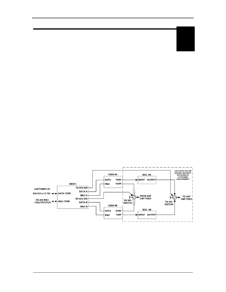
A block diagram of the signal flow is shown in Figure 2-1 below.
Figure 2-1 Functional Block Diagram