Comtech EF Data OMS11 User Manual
Page 37
Connector Pinouts
OMS11 1:1 Redundancy Switch
TM133 – Rev. 1.1
5-4
Connection to the terminal device. This is the standard configuration when shipped from factory.
Refer to Table 5-5for pinouts. Refer to Appendix A for configuring unit to RS232 Terminal.
The factory terminal setup is as follows:
Emulation Type:
VT-100 (can be changed)
Baud Rate:
9600
Data Bits:
8
Parity: No Parity (Fixed)
Stop Bits:
1 Stop Bit
The factory terminal Baud Rate can be changed by accessing dip switches located on the main
board. Internal DIP switches are accessible only by removing the top cover. Refer to Appendix
A, Figure A2.
5.4.2 Modem Remote Communications (RLLP/RS485)
The RLLP Remote Port is located on J8 allows for control and monitoring of parameters and
functions via an RS-485. Control and status messages are conveyed between the modem and all
subsidiary modems and the host computer using packetized message blocks in accordance with
a proprietary communications specification. This communication is handled by the Radyne Link
Level Protocol (RLLP), which serves as a protocol ‘wrapper’ for the RM&C data. Complete
information on monitor and control software is contained in the following sections. Refer to Table
5-5 for pinout descriptions. Refer to Appendix A for configuring the unit to RS485 Remote.
Refer to Appendix B for the RLLP Protocol.
This requires the user to first properly setup the unit ensuring Multidrop Address are configured
as needed. The OMS11 has internal DIP switches that are accessible only by removing the top
cover. DIP switch S3 is used to configure remote baud rates and addressing. Refer to Appendix
A, Figure A2 for dip switch information. If you are having trouble with DIP switch settings, contact
Radyne Customer Service for any additional help.
5.4.3 Common Equipment Faults (J8)
Common equipment fault hardware is available on the OMS11. The OMS11 M&C Connector (J8)
has Form-C contacts available that indicate which modem is online and indicates OMS11 Fault
status. Refer to Table 5-5.
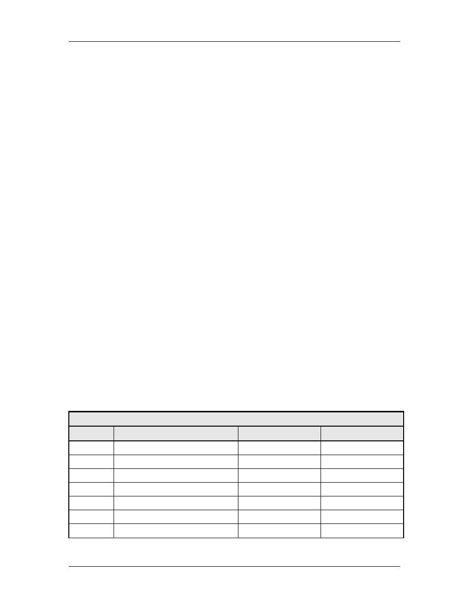
Table 5.5. Remote Monitor & Control / Faults (J8)
Pin No.
Signal Name
Signal
Direction
A
Receive Data RS-232
RXD-232
Input
B
Transmit Data RS-232
TXD-232
Output
C
Reserved
---
---
D
Transmit Data RS-485 (+)
TX-485-B
Output
E
Transmit Data RS-485 (-)
TX-485-A
Output
F
Receive Data RS-485 (+)
RX-485-B
Input
G
Receive Data RS-485 (-)
RX-485-A
Input