Appendix a. cable drawings, A.1 introduction, A.2 control interface cables – Comtech EF Data CRS-280L User Manual
Page 51
A-1
Appendix A. CABLE DRAWINGS
A.1 Introduction
This appendix contains drawings of cables used with the CRS-280L L-Band IF Switch for 1:N Redundancy. These cables are broken into two
categories – Control Interface Cables and IF Interface Cables:
• The Control Interface Cables are used to connect the CRS-280L rear panel J1 CRS Control Interface or J2 SMS Control Interface
connector to its companion redundancy switch IF Switch Control Interface connector.
• The IF Interface Cables may be selected and used to connect the CRS-280L, via the front panel Tx/Rx Type ‘N’ threaded female
connectors, to the Redundant Modem and up to 10 traffic modems that are part of the 1:N redundancy setup, as well as to any
external uplink / downlink RF equipment.
Each section provides illustrations of the cables’ technical specifications; additionally, the table in each section cross-reference to the
illustrations found in
Chapter 4. CABLES AND CONNECTIONS
.
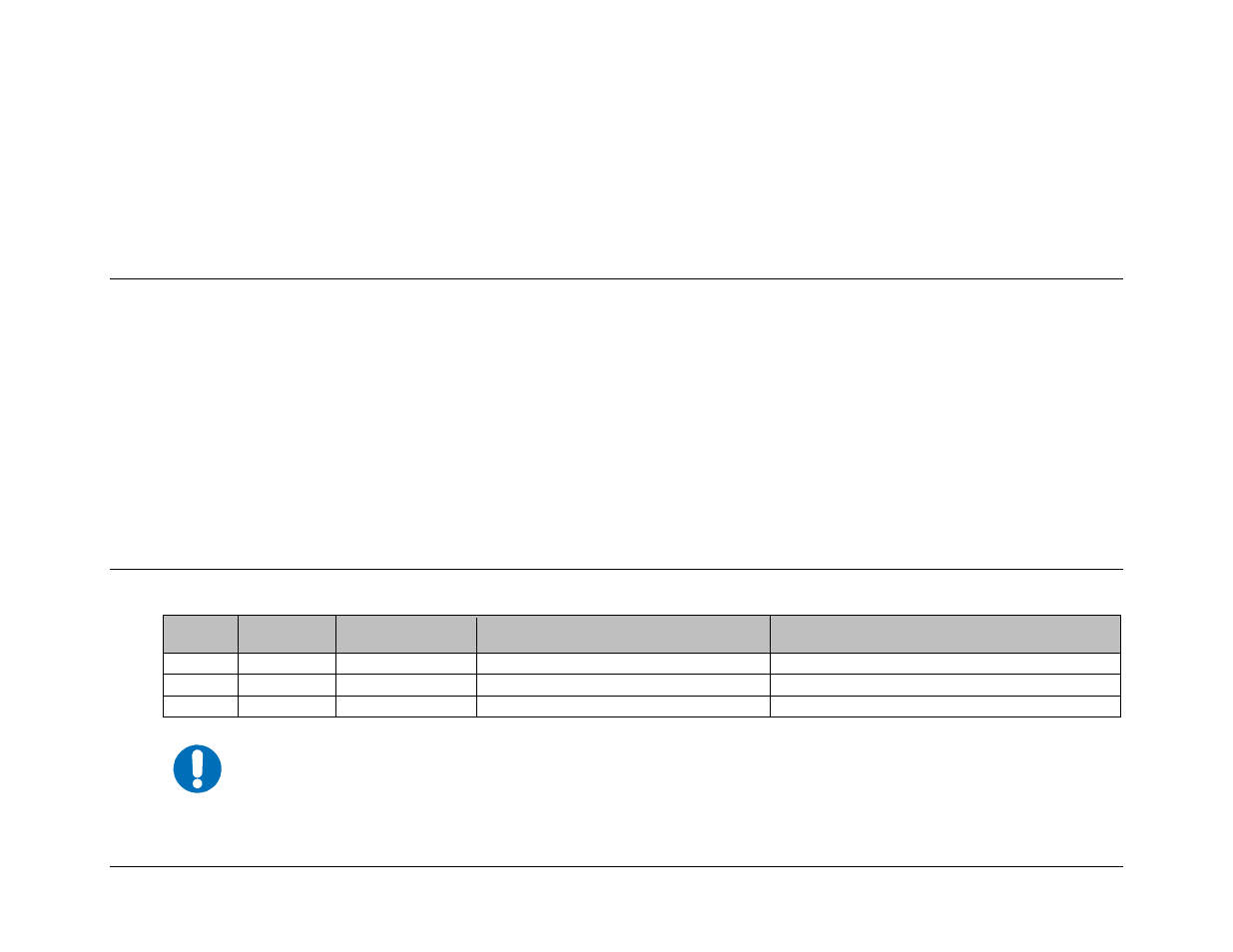
A.2 Control Interface Cables
App. A
FIG
REF Ch. 4
FIG
CEFD CABLE P/N
DESCRIPTION
USED FOR
A-1 4-1
CA/5343-1
Control Cable, DB-15F Æ DB-15M, 8’
CRS-280L Æ SMS-7000 Data Switch Unit (DSU)
A-2 4-2,
4-3
CA/WR0066
Control/Data Cable, DB-25F Æ DB-25M, 6’
CRS-280L Æ CRS-400/CRS-300
A-3 4-4
CA-0000405
Multi-drop Control Cable, DB-25M Æ (5X) DB-9F, 15’
CRS-280L Æ CRS-500 Data Switch Unit (DSU)
The Comtech EF Data SMS-7000 1:8 Modem Protection Switch and CRS-400 1:8 Redundancy Switch are legacy
products that are no longer in production.
NOTE