2 front panel connectors – Comtech EF Data CRS-280L User Manual
Page 35
CRS-280L L-Band IF Switch for 1:N Redundancy
Revision 1
Connector Pinouts
MN/CRS280L.IOM
3–3
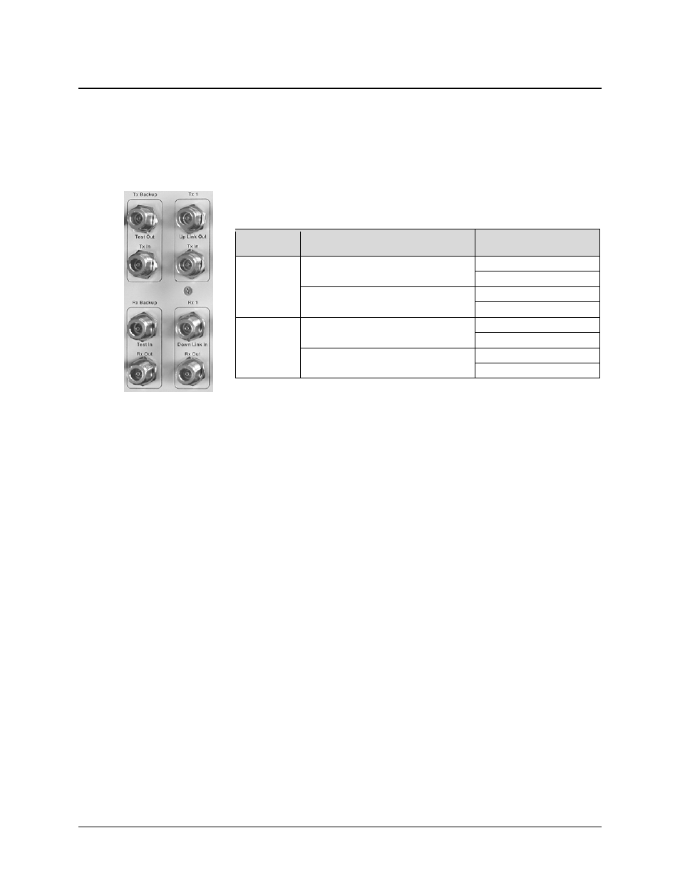
3.2 Front Panel Connectors
Unless otherwise noted, the connectors featured on the front panel of the CRS-280L are intended
for connection to all IF equipment internal and external to the 1:N redundancy setup.
3.2.1 Front Panel IF Connectors – Receive IF and Transmit IF, 50Ω Type ‘N’
Each Transmit IF and Receive IF port connector is a 50
Ω Type ‘N’ female
connector. Observe the following:
See Chapter 4. CABLES AND CONNECTIONS for complete details on IF cabling between
the CRS-280L and its companion redundant switches, redundant and traffic modems, and uplink
and downlink equipment.
IF Side
Connector
Pair
Connector Name
Transmit IF
Tx Backup (Tx Redundant)
Test Out
Tx In
Tx 1 through Tx 10 (Tx Traffic)
Up Link Out
Tx In
Receive IF
Rx Backup (Rx Redundant)
Test In
Rx Out
Rx 1 through Rx 10 (Rx Traffic)
Down Link In
Rx out
- CDD-880 (124 pages)
- CDM-800 (130 pages)
- ODMR-840 (184 pages)
- CDM-750 (302 pages)
- CDM-840 (244 pages)
- SLM-5650A (420 pages)
- CTOG-250 (236 pages)
- CDM-700 (256 pages)
- CDM-760 (416 pages)
- CDM-710G (246 pages)
- CDM-600/600L (278 pages)
- CDMR-570L (512 pages)
- CDM-625 (684 pages)
- CDM-625A (756 pages)
- CDD-564A (240 pages)
- CDD-564L (254 pages)
- CLO-10 (134 pages)
- MCED-100 (96 pages)
- CDMR-570AL (618 pages)
- CDM-600 LDPC (2 pages)
- BUC Power Supply Ground Cable (2 pages)
- MPP70 Hardware Kit for CDM-570L (4 pages)
- MPP50 Hardware Kit for CDM-570L (4 pages)
- CDM-625 DC-AC Conversion (4 pages)
- CDM-625 DC-AC Conversion with IP Packet Processor (4 pages)
- DMDVR20 LBST Rev 1.1 (117 pages)
- DMD2050E (212 pages)
- DMD-2050 (342 pages)
- DMD1050 (188 pages)
- OM20 (220 pages)
- QAM256 (87 pages)
- DD240XR Rev Е (121 pages)
- MM200 ASI Field (5 pages)
- DM240-DVB (196 pages)
- MM200 (192 pages)
- CRS-150 (78 pages)
- CRS-170A (172 pages)
- CRS-180 (136 pages)
- SMS-301 (124 pages)
- CiM-25/8000 (186 pages)
- CiM-25 (26 pages)
- CRS-500 (218 pages)
- CRS-311 (196 pages)
- CIC-20 LVDS to HSSI (26 pages)