3 crs-280l l-band if cable connections, 1 l-band if cable characteristics, L-band switch-to-modem cabling requirements – Comtech EF Data CRS-280L User Manual
Page 46: Crs-280l l-band if cable connections, 2 l-band switch-to-modem cabling requirements
CRS-280L L-Band IF Switch for 1:N Redundancy
Revision 1
Cables and Connections
MN/CRS280L.IOM
4–8
4.3
CRS-280L L-Band IF Cable Connections
Cables for connecting the CRS-280L L-Band IF Switch to the L-Band modems within the
redundancy system are available for purchase from Comtech EF Data and can be ordered at the
same time the order is placed for the CRS-280L:
CEFD Part No.
Description
CA/RF10453-2
Cable Assembly, L-Band 50
Ω, Type ‘N’ male to Type ‘N’ male connectors, 2’
CA/RF10453-4
Cable Assembly, L-Band 50
Ω, Type ‘N’ male to Type ‘N’ male connectors, 4’
CA/RF10453-6
Cable Assembly, L-Band 50
Ω, Type ‘N’ male to Type ‘N’ male connectors, 6’
CA/RF10453-8
Cable Assembly, L-Band 50
Ω, Type ‘N’ male to Type ‘N’ male connectors, 8’
4.3.1
L-Band IF Cable Characteristics
IMPORTANT
If L-Band cables are not purchased from Comtech EF Data, use of a suitable
equivalent is recommended.
Cable Type
Loss at 1GHz
Loss at 2GHz
Semflex BPE200 (or equivalent)
0.11 dB/ft
0.15 dB/ft
4.3.2
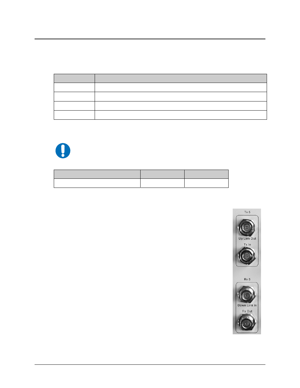
L-Band Switch-to-Modem Cabling Requirements
The number of cables required depends on the switch system configuration. Per
the example shown at right, each modem connected to the CRS-280L front panel
requires two L-Band cables:
• One cable for the Rx L-Band connection
• One cable for the Tx L-Band connection
Each cable must be connected and secured using the Type ‘N’ threaded female
connectors on the front panel of the CRS-280L and rear panel of the L-Band
modems.