International symbols, Emc (electromagnetic compatibility), En55022 - 1997 compliance – Comtech EF Data CRS-280L User Manual
Page 14: En55024 - 1998 compliance
CRS-280L L-Band IF Switch for 1:N Redundancy
Revision 1
Preface
MN/CRS280L.IOM
x
The CRS-280L is designed for connection to a power system that has separate ground, line and
neutral conductors. The equipment is not designed for connection to a power system that has no
direct connection to ground.
The CRS-280L is shipped with line inlet cables suitable for use in the country of operation. If it is
necessary to replace these cables, ensure the replacement has an equivalent specification.
Examples of acceptable ratings for the cable include HAR, BASEC and HOXXX-X. Examples of
acceptable connector ratings include VDE, NF-USE, UL, CSA, OVE, CEBEC, NEMKO,
DEMKO, BS1636A, BSI, SETI, IMQ, KEMA-KEUR and SEV.
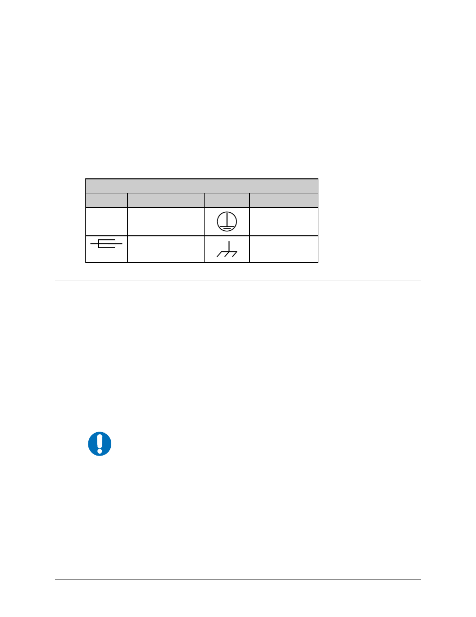
International Symbols
International Symbols
Symbol
Definition
Symbol
Definition
~
Alternating Current
Protective Earth
Fuse
Chassis Ground
EMC (Electromagnetic Compatibility)
This is a Class A product. In a domestic environment, it may cause radio interference that
requires the user to take adequate protection measures.
EN55022 - 1997 Compliance
This equipment meets the radio disturbance characteristic specifications for information technology
equipment as defined in EN55022-1997.
EN55024 - 1998 Compliance
This equipment meets the EMC/immunity characteristics for the limits and methods of measurement
for information technology equipment per EN55024-1998.
IMPORTANT
To ensure that the CRS-280L continues to comply with these standards,
observe the following instructions:
• Connections to the transmit and receive IF ports (‘N’ type female connectors) should be made
using a good quality coaxial cable; for example, RG213/U.
• The 'D' type connector attached to the rear panel must have a back-shell that provides
continuous metallic shielding. Cable with a continuous outer shield (either foil or braid, or
both) must be used, and the shield must be bonded to the back-shell.
• The equipment must be operated with both AC module panels assembled firmly to the rear of
the chassis at all times. If it becomes necessary to remove either AC module, the user should
ensure that the cover is correctly re-fitted before normal operation commences.