1 compatibility – Comtech EF Data CRS-280L User Manual
Page 20
CRS-280L L-Band IF Switch for 1:N Redundancy
Revision 1
Introduction
MN/CRS280L.IOM
1–2
Splitter
Splitter
Splitter
Splitter
Splitter
Splitter
Splitter
Splitter
Splitter
Splitter
Rx1
Rx2
Rx3
Rx4
Rx5
Rx6
Rx7
Rx8
Rx9
Rx10
Tx2
Tx1
Tx3
Tx4
Tx5
Tx6
Tx7
Tx8
Tx9
Tx10
Backup
Modulator
Control
Interface
& Drivers
Test
Out
Test
In
Redundant
Power
Downlink Inputs
Prime Modulators
Prime Demodulators
Backup
Demodulator
Uplink Outputs
A
B
CRS
SMS
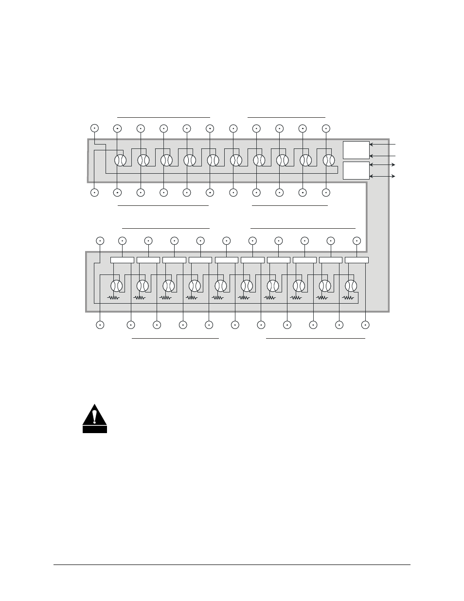
has a transmit section with TX input / uplink output and a receive section with Rx output /
downlink input.
Figure 1-2 depicts the system level block diagram for a CRS-280L-equipped 1:10 redundancy
system.
Figure 1-2. 1:10 Redundancy w/CRS-280L – System-level Block Diagram
1.1.1 Compatibility
CAUTION
1. The Comtech EF Data CRS-280L L-Band IF Switch is designed specifically as
an accessory product for Comtech EF Data equipment. It is
not
designed to
operate with any other manufacturer's equipment.
2. The CRS-280L is not designed to convey DC power to external equipment such
as LNBs or BUCs. Do
not
apply DC power to the L-Band input and output
(Type ‘N’) ports of the switch. In addition, the CRS-280L is not designed to
pass to 10 MHz reference or FSK signaling.