3 l-band uplink/downlink cable connections – Comtech EF Data CRS-280L User Manual
Page 47
CRS-280L L-Band IF Switch for 1:N Redundancy
Revision 1
Cables and Connections
MN/CRS280L.IOM
4–9
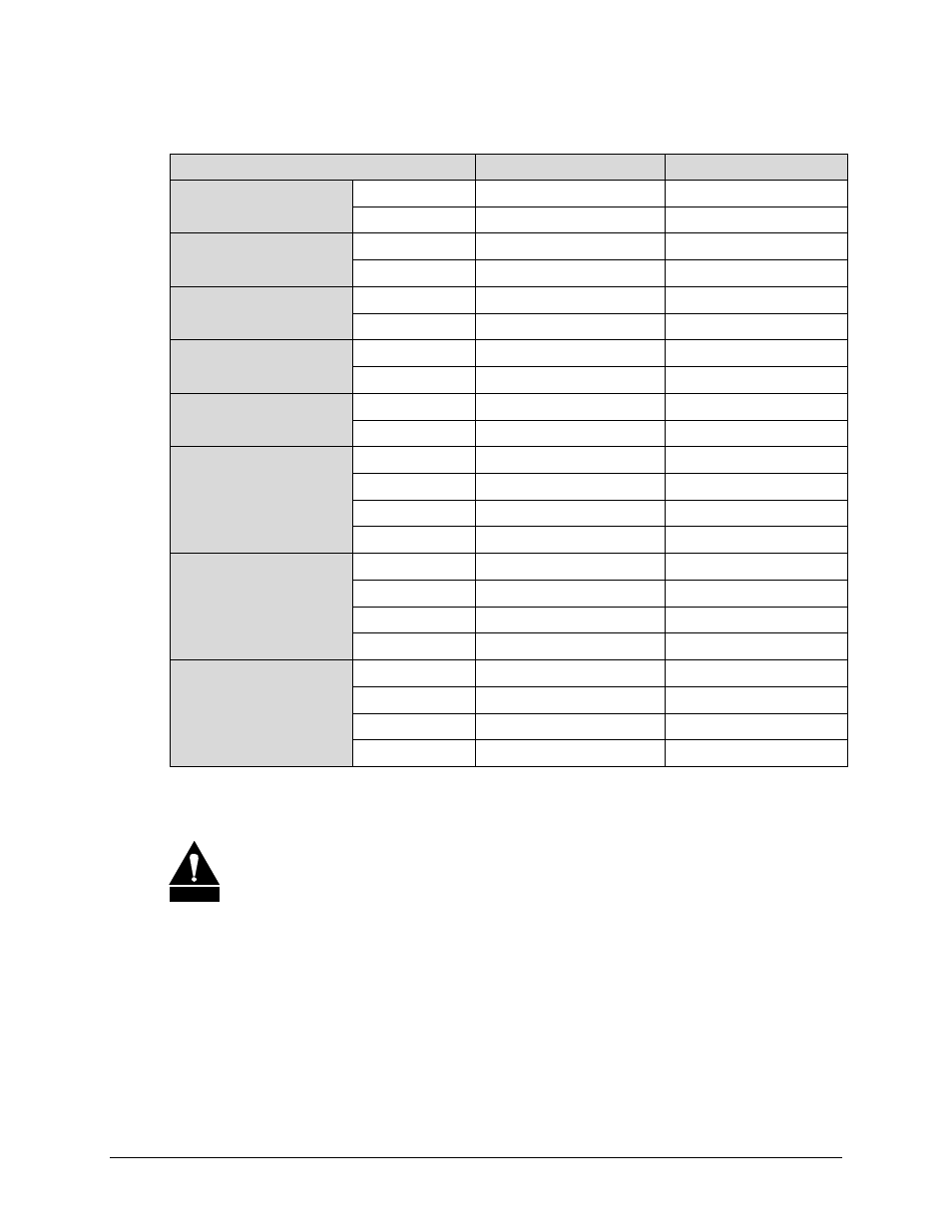
Cable connections are defined as follows:
L-Band Modem Connection
CRS-280L Connection
Comments
Redundant Modem
TX Output
↔
TX Backup (TX In)
RX Input
↔
RX Backup (RX Out)
Prime Modem #1
TX Output
↔
TX 1 (TX In)
RX Input
↔
RX 1 (RX Out)
Prime Modem #2
TX Output
↔
TX 2 (TX In)
RX Input
↔
RX 2 (RX Out)
Prime Modem #3
TX Output
↔
TX 3 (TX In)
RX Input
↔
RX 3 (RX Out)
Prime Modem #4
TX Output
↔
TX 4 (TX In)
RX Input
↔
RX 4 (RX Out)
Prime Modem #5
TX Output
↔
TX 5 (TX In)
RX Input
↔
RX 5 (RX Out)
Prime Modem #6
TX Output
↔
TX 6 (TX In)
RX Input
↔
RX 6 (RX Out)
Prime Modem #7
TX Output
↔
TX 7 (TX In)
RX Input
↔
RX 7 (RX Out)
Prime Modem #8
TX Output
↔
TX 8 (TX In)
RX Input
↔
RX 8 (RX Out)
Prime Modem #9
TX Output
↔
TX 9 (TX In)
RX Input
↔
RX 9 (RX Out)
Prime Modem #10
TX Output
↔
TX 10 (TX In)
RX Input
↔
RX 10 (RX Out)
4.3.3 L-Band Uplink/Downlink Cable Connections
CAUTION
The CRS-280L is not designed to convey DCpower to external equipment such as
LNBs or BUCs. Do not apply DC power to the L-Band input and output (Type ‘N’)
ports of the switch.
CEFD recommends that connections to uplink and downlink equipment be made after all other
system cabling and configuration is complete. Cabling to and from the CRS-280L uplink and
downlink ports is dependant on the system configuration and the uplink/downlink equipment
used. For additional information, refer to the uplink/downlink equipment documentation.