2 crs-280l control cable connections – Comtech EF Data CRS-280L User Manual
Page 40
CRS-280L L-Band IF Switch for 1:N Redundancy
Revision 1
Cables and Connections
MN/CRS280L.IOM
4–2
4.2
CRS-280L Control Cable Connections
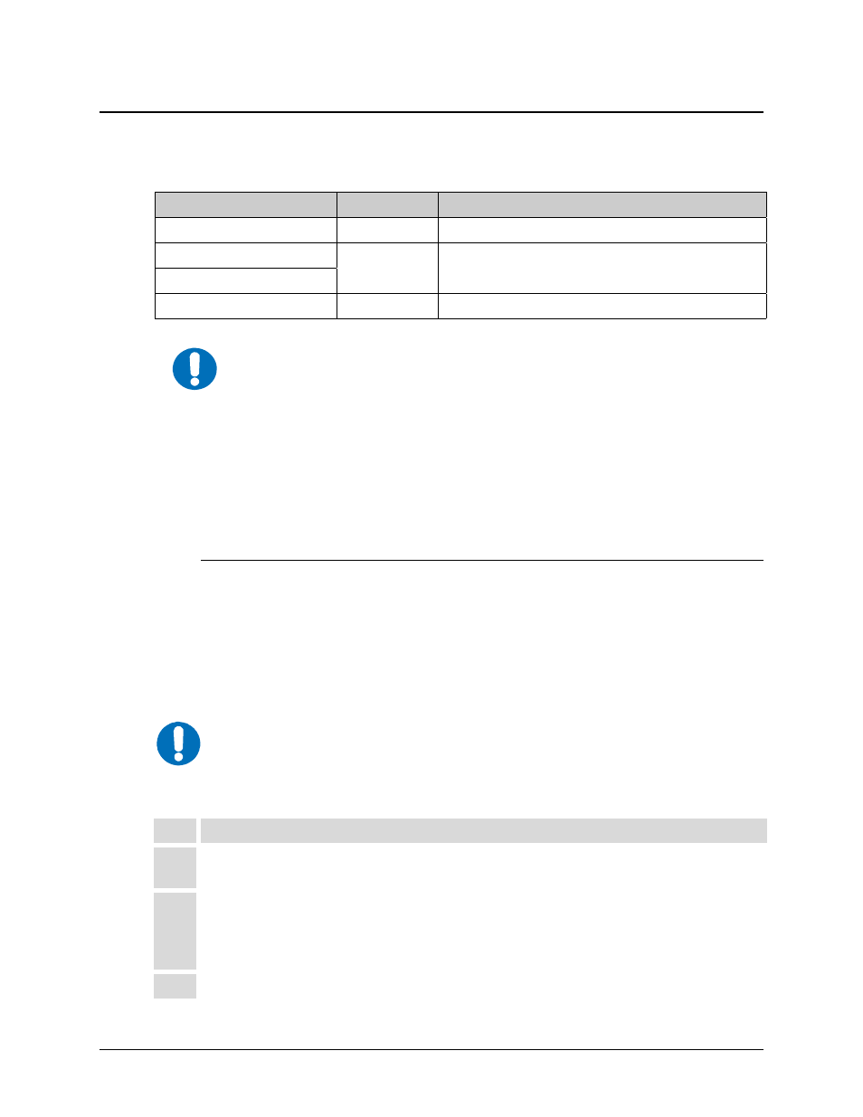
Each CRS-280L is supplied with a control cable for connection to the associated 1:N Redundancy
Switch control unit. The control cable must be specified at time of order:
1: N Redundancy Switch
CEFD Part No.
Description
SMS-7000**
CA/5343-1
Control Cable, DB-15F Æ DB-15M, 8’
CRS-400**
CA/WR0066
Control Cable, DB-25M Æ DB-25F, 6’
CRS-300
CRS-500
CA-0000405
Multi-drop Control Cable, DB-25M Æ(4X) DB-9F, 15’)
** Indicates a Comtech EF Data legacy product that is no longer in production
IMPORTANT
1. When connecting the Control cable between the CRS-280L and the
redundancy switch, ensure that screw locks on the ‘D’ type connectors are
securely fastened. This will prevent the accidental unmating of the cable,
particularly when a standby unit is being removed or replaced.
2. Only one control interface must be used. Do not make connections to
both control interfaces on the CRS-280L. The CRS-280L automatically
detects the control interface in use and cannot function with both control
cables connected.
Connect the supplied cable between the Redundancy Switch (controller) and the CRS-280L (refer
to the pertinent Redundancy Switch Installation and Operation Manual for additional information):
For CRS-280L
Æ
Refer to:
SMS-7000 1:8 Modem Protection Switch**
Sect. 4.2.1
CRS-400 1:8 HSSI Redundancy Switch**
Sect. 4.2.2
CRS-300 1:N Redundancy Switch
Sect. 4.2.3
CRS-500 M:N Redunancy System
Sect. 4.2.4
4.2.1
SMS-7000 1:8 Modem Protection Switch Control Cable Connection
The Comtech EF Data SMS-7000 1:8 Modem Protection Switch is a legacy
product that is no longer in production.
Step Instructions
1
Connect the DB-15F connector on the CA/5343-1 Control Cable to the DB-15M J2 SMS
Control Interface port on the rear panel of the CRS-280L.
2
Connect the DB-15M connector on the CA/5343-1 Control Cable to the DB-15F J12 IF
Control Interface port on the Control/Modem side of the SMS-7000 Data Switch Unit
(DSU).
Note: The CRS-280L serves to replace, in its entirety, the SMS-7000 IF Switch Unit (IFU).
3
Secure the cable by tightening the screw locks on both ends of the control cable.
NOTE