Maintenance – Beisler 1265-4 User Manual
Page 61
Service Instructions Automatic Single-Head Serging Machine 1265-4
Beisler GmbH
C-25
C.5.18 Adjusting the stepper motor PCB
The PCB that controls the stepper motor is installed in the switchbox.
NOTE - Machine cycle!
Prior to a replacement of the PCB, the machine should be moved ma-
nually back to its basic position to prevent collisions among moving ma-
chine components when the machine is switched back on.
1. Depressurize the compressed-air system of the machine and
disconnect the compressed-air hose of the machine from the on
site compressed-air supply system.
2. Move the cross transport to its basic position.
CAUTION - Damage to electrical components!
The positions of switches on the PCB must not be
changed as otherwise the affected electrical compon-
ents can be damaged or become unusable!
Disconnect the machine from the power supply system
and protect it from accidental reconnection.
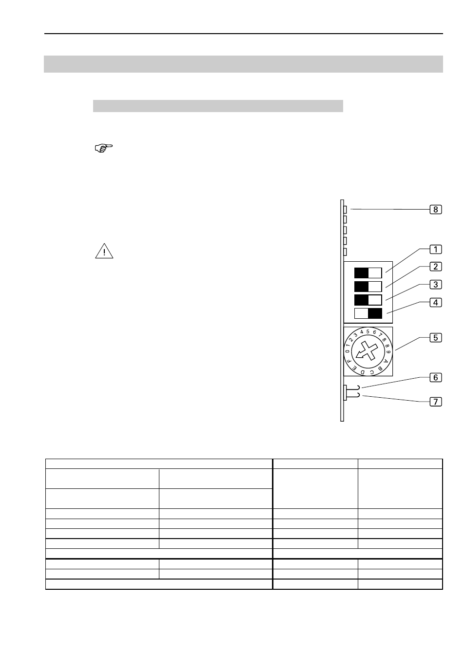
Fig. 16: Setting the PCB switches:
1. Set the step number:
at the DIP switches 1 and 2,
microstep at the hook switches 6 and 7.
2. Set current lowering at DIP switch 3.
3. Set DIP switch 4 to ON.
4. Set motor phase current by rotating knob 5 to position F.
5. Switch on supply voltage. When the PCB has been set correct-
ly, the LED 8 (ready) illuminates, the ready relay is energized.
C.5
Maintenance
Fig. 16
DIP switch 1
DIP switch 2
200
2000
ON
OFF
400
4000
ON
ON
500
5000
OFF
ON
1000
100000
OFF
OFF
Rotating knob position
Phase current
DIP switch 3
Current lowering
F
5.50 A
OFF
ON
ON
OFF
Microstep
Signal 0 = deenergized, Signal 1 = current-carrying
Hook switch
open
Signal = 0
Hook switch
closed
Signal = 1
Hook switch
closed
Signal = 0
Hook switch
open
Signal = 1