Start-up – Beisler 1265-4 User Manual
Page 42
Service Instructions Automatic Single-Head Serging Machine 1265-4
Beisler GmbH
C-6
C.3
Start-up
C.3.1 Aligning the machine table
After the machine has been installed at the desired location, the machi-
ne table must be aligned:
Set machine table to required height.
Level machine table horizontally on all sides.
Setting the table height:
1. Fig. 1: Lift machine: Connect lifting device at lift points (arrows) be-
low the crossmembers. If the machine is equipped with the optional
transport rollers, release brakes before lifting.
2. Loosen locating screws 2 on all table legs.
3. Pull table legs 4 out to the desired length and retighten locating
screws.
4. Tighten height adjustment locating screws 2.
5. Lower machine onto floor.
6. Level worktable horizontally in all directions.
7. Tighten height adjustment locating screws 2.
NOTE - Shipping braces
Before the machine is connected to the power supply sy-
stem and operated, all shipping braces must be removed.
Cut off cable ties.
Remove labels.
Remove protective film from operating panel.
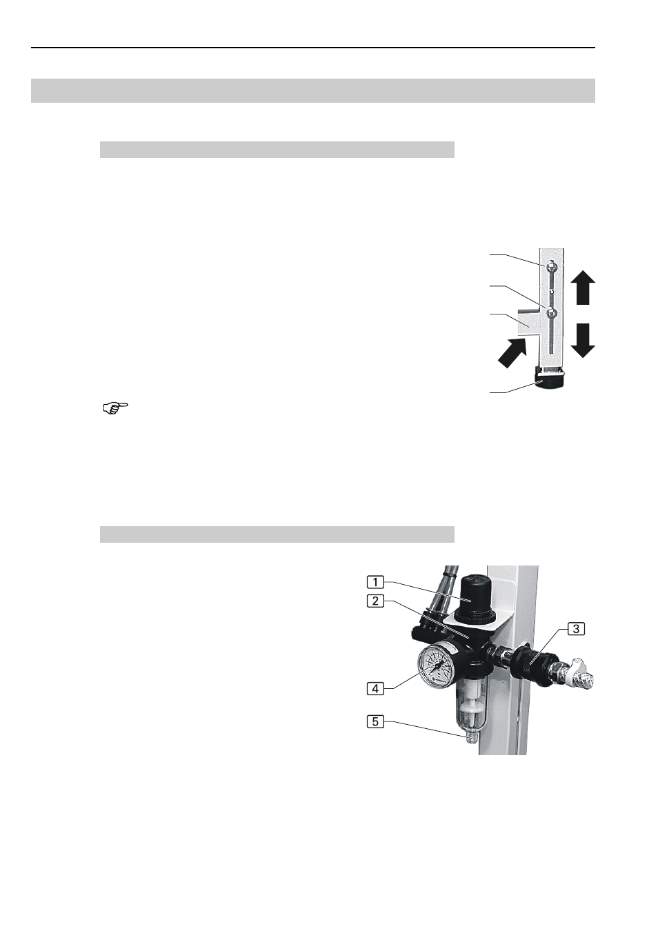
C.3.2 Compressed-air connections
Fig. 2: The compressed-air connection is preinstal-
led on the machine. It comprises the following com-
ponents:
Pressure reducer 2 with manometer 4 and
water separator 5,
Pressure hose with push-in plug 3.
The pressure reducer ist installed to the machine
frame.
Connecting the machine to the compressed-air
supply system:
1. Connect pressure hose plug to on-site terminal
unit.
2. Open on-site compressed-air supply.
3. Set pressure reducer to a machine operating
pressure of 6 bar by rotating pressure reducer
knob 1 and read value on manometer 4:
To increase pressure, rotate in the clockwise direction.
To reduce pressure, rotate in the counterclockwise direction.
Fig. 1
Fig. 2