Spi-pdi-interface, Distributed clocks, Table 14 pinout of the connectors tp204 and j204 – BECKHOFF EL9800 Basisplatine User Manual
Page 24: 7 spi-pdi-interface, 8 distributed clocks
Product overview
22
EL9800
2.7 SPI-PDI-Interface
Similar to the µ-Controller interface this interface only consists of two connectors (TP204 and J204),
which can as well be used as test points as for connection with external hardware. Again the pinout of
both connectors is identical and therefore listed in Table 14.
Table 14 Pinout of the connectors TP204 and J204
Pin
Signal
Pin
Signal
1
SPI_CLK_IN
2
3.3V
3
EEPROM_LOADED
4
SYNC0/LATCH0
5
SPI_DIN
6
SPI_SEL
7
SPI_DOUT
8
SYNC1/LATCH1
9
SPI_INTERRUPT
10
GND
The maximum achievable data transfer rates using this interface are depending mainly from the Ether-
CAT-Slave-Controller used in combination with the EL9800 base board. Data transfer rates are also de-
pending on the bus driver (SN74LVC245A from Texas Instruments) used on the base board. Details in-
formation about these rates can be found in both devices datasheets.
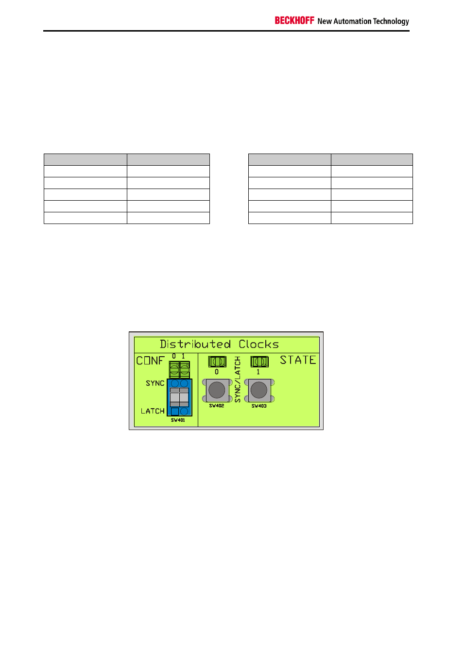
2.8 Distributed Clocks
Figure 14 Configuration and Status-Area of the Distributed Clocks
In the configuration area of the distributed clocks the user can switch from Sync- to Latch- signal configu-
ration. That means using the switch SW401, one can switch from Sync0 to Latch0 and from Sync1 to
Latch1 separately. Switching from Sync to Latch configuration and vice versa, only changes the driving
direction of the bus drivers on the EL9800 base board. The EtherCAT postage stamp has to be config-
ured equivalently in order to prevent damage either from the postage stamp as well as from the EL9800
base board. Sync configuration is indicated by activated LEDs above the switch SW401.
In the right section of the Distributed Clocks area the state of the Sync/Latch signals is indicated by LEDs,
which are active if the corresponding Sync/Latch signal has the logical state one. Additionally manual
chance of the Sync/Latch signal is possible by pressing the buttons SW402 and SW403