Table 11 pinout of the connectors tp209 and j209, N table 11 – BECKHOFF EL9800 Basisplatine User Manual
Page 22
Product overview
20
EL9800
tween PIC and EtherCAT postage stamp is realized using the SPI-Interface. Additionally an EEPROM
(U1004, Type: AT24C16A) is connected to the PIC using the I²C-Interface. Furthermore a crystal (X1000)
with 24 MHz resonant frequency is also connected with the PIC.
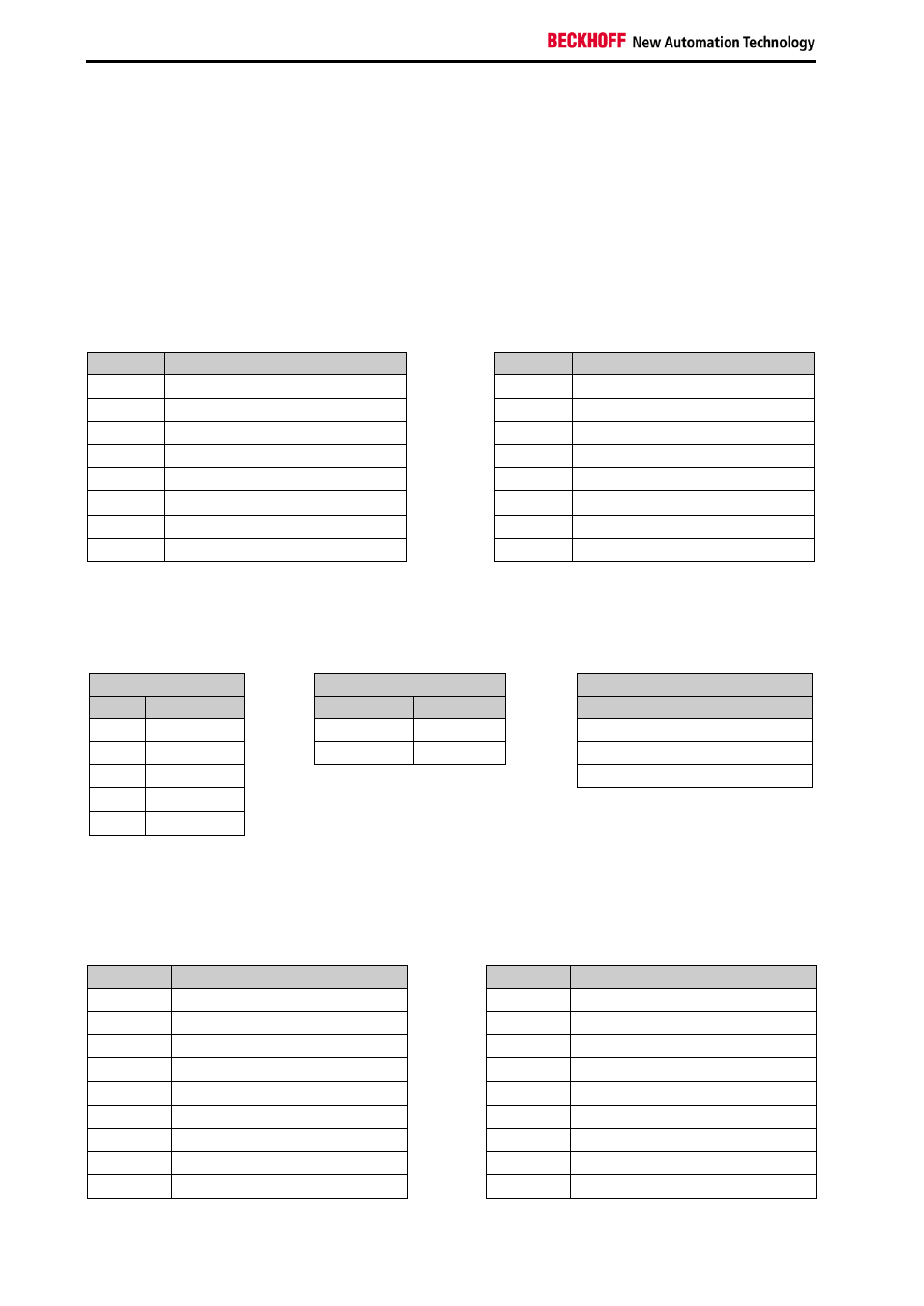
For demonstration and testing purposes digital in- and outputs and an analogue input connected with the
PIC are available. Eight LEDs and eight Switches each are building the digital interface of the PIC( pinout
see Table 9). The analogous input is connected to the Port RB3 of the PIC.
State and error indication is available by the LEDs connected to the ports RF1 (RUN) and RF0 (ERR) of
the PIC.
Table 9 Location of the inputs and output ports on the PIC-
Port
Signal
Pin
Signal
RB8
Digital Output Bit 0
RD0
Digital Input Bit 0
RB9
Digital Output Bit 1
RD1
Digital Input Bit 1
RB10
Digital Output Bit 2
RD2
Digital Input Bit 2
RB11
Digital Output Bit 3
RD3
Digital Input Bit 3
RB12
Digital Output Bit 4
RD4
Digital Input Bit 4
RB13
Digital Output Bit 5
RD5
Digital Input Bit 5
RB14
Digital Output Bit 6
RD6
Digital Input 6
RB15
Digital Output Bit 7
RD7
Digital Input 7
SPI pinout, EEPROM pinout and the pinout of the programming interface are available (see Table 9).
Table 10 Connection of SPI-interface, EEPROM and programming interface with the PIC24H
SPI-Interface
EEPROM- Interface
Programming Signals
Port
Signal
Port
Signal
Port
Signal
RB2
SPI_SEL
RG2/SCL1
EE_CLK
RB0/PGD3 TARGET_DATA
RD8
SPI_IRQ
RG3/SDA1
EE_SDA
RB1/PGC3 TARGET_CLOCK
RF2
SPI_DOUT
MCLK#
TARGET_VPP
RF3
SPI_DIN
RF6
SPI_CLK
The connectors TP209 and J209 are connected with the Port of the PICs and can be used as test points
and for interfacing with external hardware. The connectors TP209 and J209 pinout is shown in Table 11.
Table 11 Pinout of the connectors TP209 and J209
Port
Signal
Port
Signal
1
GND
2
3.3V
3
PGD3/RB0
4
PGC3/RB1
5
AN2/SS1/CN4/RB2
6
AN3/CN5/RB3
7
AN4/IC7/CN6/RB4
8
AN5/IC8/CN7/RB5
9
PGC1/RB6
10
not connected
11
GND
12
3.3V
13
U2CTS/AN8/RB8
14
AN9/RB9
15
TMS/AN10/RB10
16
TDO/AN11/RB11
17
TCK/AN12/RB12
18
TDI/AN13/RB13