Pic pdi-interface, Table 8 pinout of the connector j900, Figure 12 voltages on the headers tp207 und j207 – BECKHOFF EL9800 Basisplatine User Manual
Page 21: Figure 13 pic pdi-interface, 6 pic pdi-interface
Product overview
EL9800
19
Additional signals are available on the connector J900 (Table 8).
Table 8 Pinout of the connector J900
Pin Signal
1
VCC
2
WD_STATE
3
OE_CONF
4
GND
2
VCC
GND
1
Pin Number
50
49
1
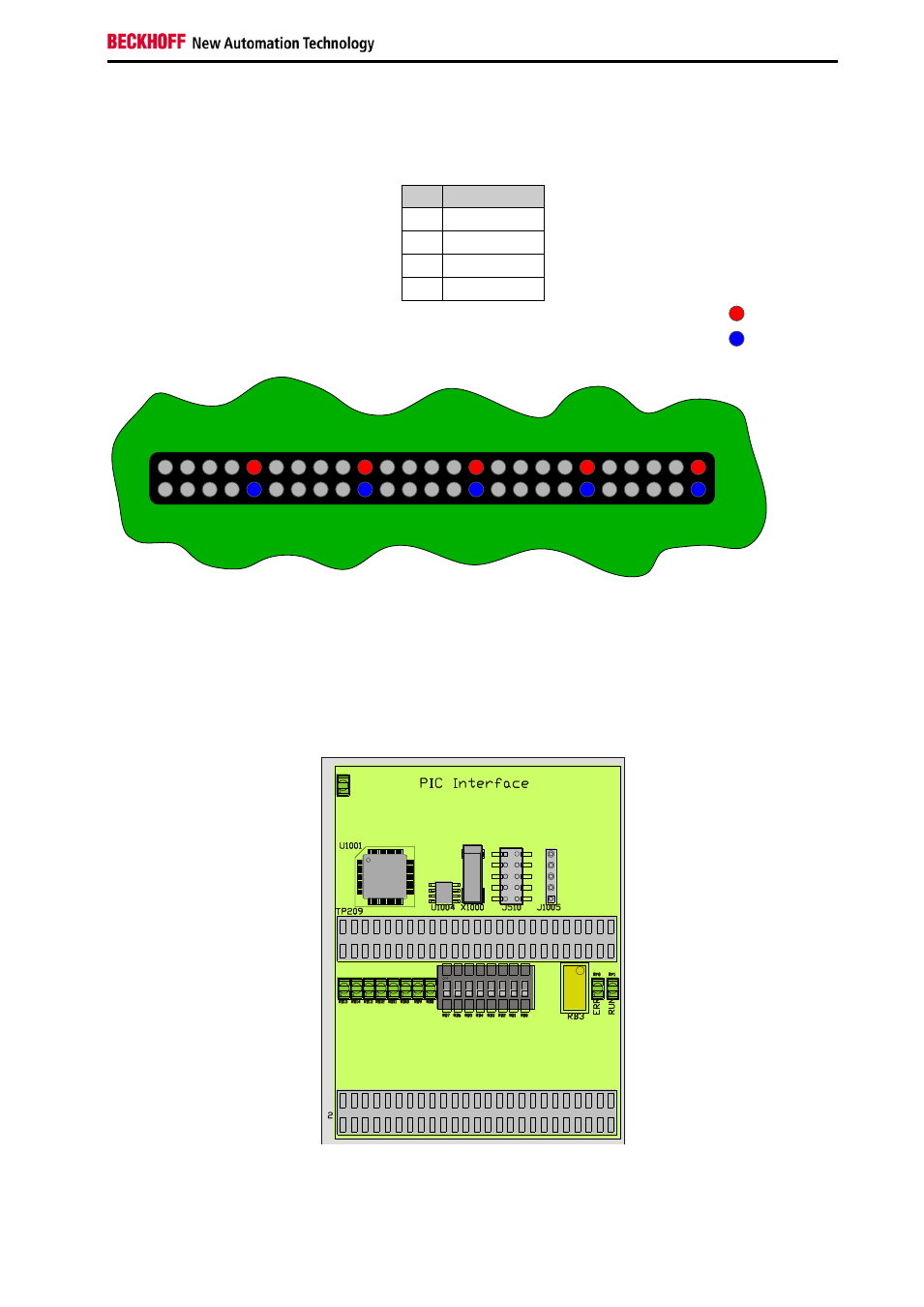
Figure 12 Voltages on the headers TP207 und J207
The headers TP208 and J208 (see Figure 12) have an identical signal layout. While header TP207 is
mostly used as test points, J207 can be used interfacing external circuits.
2.6 PIC PDI-Interface
Figure 13 PIC PDI-Interface
On the EL9800 base board a 24HJ128 PIC (U1001) from Microchip is integrated. Communication be-
See also other documents in the category BECKHOFF Equipment:
- EP-xxxx-xxxx (19 pages)
- Bus Terminal System (19 pages)
- BK2000 (30 pages)
- LC3100 (67 pages)
- BK4000 (28 pages)
- BK3xx0 (95 pages)
- BK5000 (12 pages)
- LC5200 (32 pages)
- BK7000 (29 pages)
- BK7500 (32 pages)
- BK7300 (40 pages)
- BK8100 (26 pages)
- BC2000 (28 pages)
- BC3100 (51 pages)
- BC7300 (48 pages)
- BC8100 (36 pages)
- BC3150 (112 pages)
- KL1012 (2 pages)
- KL1114 (2 pages)
- KL1164 (1 page)
- KL1232-xxxx (4 pages)
- KL1501 (19 pages)
- KL1512 (15 pages)
- KL2521-0024 (18 pages)
- KL2512 (21 pages)
- KL2612 (4 pages)
- KL2622 (9 pages)
- KL3062 (24 pages)
- KL3064 (20 pages)
- KL4132 (19 pages)
- KL4034 (25 pages)
- KL3302 (23 pages)
- KL3351 (18 pages)
- KS3681 (43 pages)
- KL4112 (18 pages)
- KL5001 (16 pages)
- KL5051 (17 pages)
- KL5101-0012 (21 pages)
- KS5111-0000 (21 pages)
- KL5121 (19 pages)
- KL6021 (20 pages)
- KL6051 (17 pages)
- Z1000 (2 pages)
- KL6071 (12 pages)
- Z1003 (2 pages)